
Method and system for remote software debugging

a software debugging and remote technology, applied in the field of remote software debugging, can solve the problems of time-consuming and frustrating for programmer, large hindering the software debugging process, and inconvenient changing cables in this manner, and achieve the effect of quick and easy establishmen

Active Publication Date: 2009-06-02
AMERICAN MEGATRENDS
View PDF110 Cites 50 Cited by
  • Summary
  • Abstract
  • Description
  • Claims
  • Application Information

AI Technical Summary

Benefits of technology

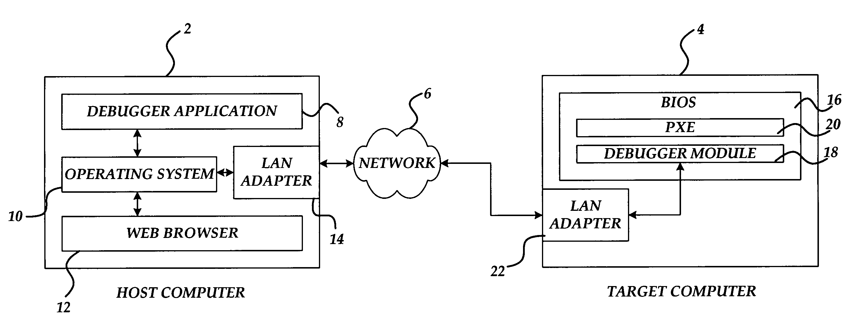
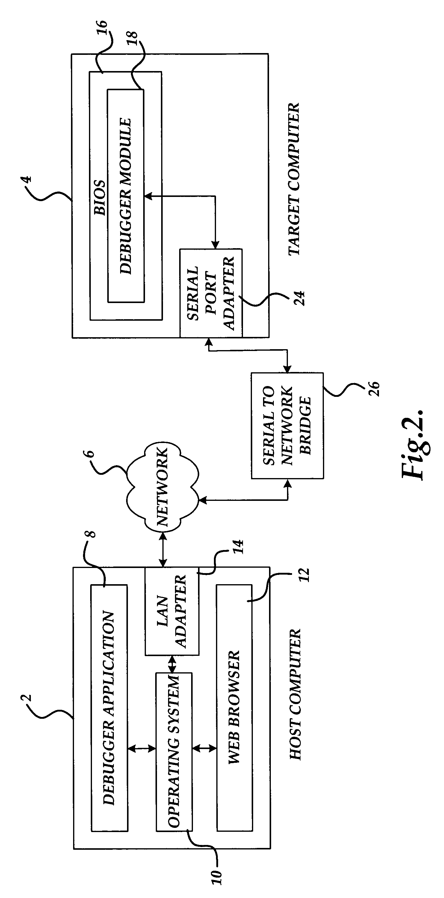
[0007]In accordance with the present invention, the above and other problems are solved by methods and systems for remotely debugging a software program. The systems make use of a debugger application executing on a host computer and configured to communicate with a debugger module executing on a target computer via a distributed computing network, such as the Internet. By allowing the debugger application executing on the host computer to communicate over a standard network connection with the debugger module executing on the target computer, the physical limitations of previous solutions utilizing locally-connected non-network cables to connect the host and target computers are overcome. Moreover, because a standard network connection is utilized between the debugger application executing on the host computer and the debugger module executing on the target computer, a new network connection with a different target computer may be quickly and easily established without the need to physically relocate cables.

Problems solved by technology

This, however, greater hinders the software debugging process because the programmer performing the debugging must be in close proximity to the system being debugged.
However, these systems also require that the programmer be in relatively close proximity to the system being debugged.
This may be extremely inconvenient when it is necessary to debug a computer system that is located across the country or even across the world.
Changing cables in this manner can be time consuming and frustrating for the programmer responsible for debugging the target computer.

Method used


Image

  • Method and system for remote software debugging
  • Method and system for remote software debugging
  • Method and system for remote software debugging

Examples


Embodiment Construction

[0018]As described briefly above, embodiments of the present invention provide methods and systems for remotely debugging a computer software program. In the following detailed description, references are made to the accompanying drawings that form a part hereof, and in which are shown by way of illustration specific embodiments or examples. These embodiments may be combined, other embodiments may be utilized, and structural changes may be made without departing from the spirit and scope of the present invention. The following detailed description is, therefore, not to be taken in a limiting sense, and the scope of the present invention is defined by the appended claims and their equivalents.

[0019]Referring now to the drawings, in which like numerals represent like elements throughout the several figures, aspects of the present invention and the exemplary operating environment will be described. FIGS. 1-3 and the following discussion are intended to provide a brief, general descript...


PUM


Abstract

Methods and systems for remotely debugging a software program are provided. The methods and systems make use of a debugger application executing on a host computer and configured to communicate with a debugger module executing on a target computer via a distributed computing network, such as the Internet.

Description

CROSS-REFERENCE TO RELATED APPLICATIONS[0001]This application claims the benefit of provisional U.S. Patent application No. 60 / 483,382, entitled “Method and System For Remote Software Debugging”, filed on Jun. 27, 2003, the entire contents of which is expressly incorporated herein by reference.TECHNICAL FIELD[0002]Embodiments of the invention relate generally to the field of software debugging. More particularly, embodiments of the invention relate to the field of debugging software remotely.BACKGROUND OF THE INVENTION[0003]One of the most important parts of the software development process is the process of debugging. Debugging refers to the process of identifying and eliminating errors within a software program. A debugging application program, called a debugger, provides tools to assist a programmer in locating and correcting program errors. For instance, most debuggers provide tools for stepping through the executing code of a program, monitoring the status of input / output ports...

Claims


Application Information

Patent Timeline
Patent Type & Authority Patents(United States)
IPC IPC(8): G06F9/44G06F11/00G06F15/177
CPCG06F11/3664G06F11/362
Inventor RIGHI, STEFANOMILLS, ERIC
Owner AMERICAN MEGATRENDS
Learn More