Sprinkler head cover and a sprinkler head

a sprinkler head and cover technology, applied in watering devices, horticulture, agriculture, etc., can solve the problems of long time required for the actuation of the sprinkler head, variation in connection strength, and difficulty in adjusting the connection strength, so as to facilitate the separation of the cover plate, improve the adhesion, and reduce the connection strength

Inactive Publication Date: 2009-06-09
SENJU SPRINKLER
View PDF19 Cites 10 Cited by
  • Summary
  • Abstract
  • Description
  • Claims
  • Application Information

AI Technical Summary

Benefits of technology

[0036]Further, if the coating film comprising the material having an excellent adhesion to the low melting point alloy being applied to the cover plate connecting surface of the housing, it becomes possible to prevent, after the housing having been connected with the cover plate, the housing from being separated from the low melting point alloy, resulting in the lower connection strength.
[0037]The leaf spring is disposed in order to facilitate the separation of the cover plate from the mount to allow the cover plate to drop off in the case of fire, and the leaf spring that is folded in three, can help increase an actuation stroke to be greater than that achieved by the spring folded in two.
[0038]Especially, in a case of the cover plate defining the curved surface, since the curved surface of the cover plate, which the leaf spring is placed in contact with, is not extending in parallel with the housing bottom surface, making the actuation stroke greater by employing the leaf spring folded in three is more advantageous to obtain the actuation stroke sufficient to separate the cover plate from the mount upon melting of the low melting point alloy.
[0039]In addition, with the aid of the cuff (pawl) disposed in the end of the housing contact surface of the leaf spring, which is adapted to engage with the peripheral edge of the housing, the leaf spring can be prevented from slipping into the inside of the cover plate or out of the housing, so that the leaf spring can be always held in an appropriate position.

Problems solved by technology

A disadvantage of this design is that it may be difficult for the hot air stream from the fire to reach the sprinkler head disposed deep inside the housing after the disengagement of the cover plate under the fire, requiring a long time to trigger the sprinkler head to be actuated.
However, due to a shape of the cover plate that has employed the bowl-like configuration, a site of connection between the cover plate and the housing necessarily defines an inclined-face and the inclined-face should allow the molten low melting point alloy to flow down along the inclined surface of the cover plate during soldering work, thus making it problematic to carry out the soldering work, which could lead to a variation in connection strength depending on the specific skill of the worker.
If a quantity of the low melting point alloy is insufficient or a connection area is not large enough in the site of connection between the cover plate and the housing, the connection strength would be consequently low.

Method used


Image

  • Sprinkler head cover and a sprinkler head
  • Sprinkler head cover and a sprinkler head
  • Sprinkler head cover and a sprinkler head

Examples


embodiment 1

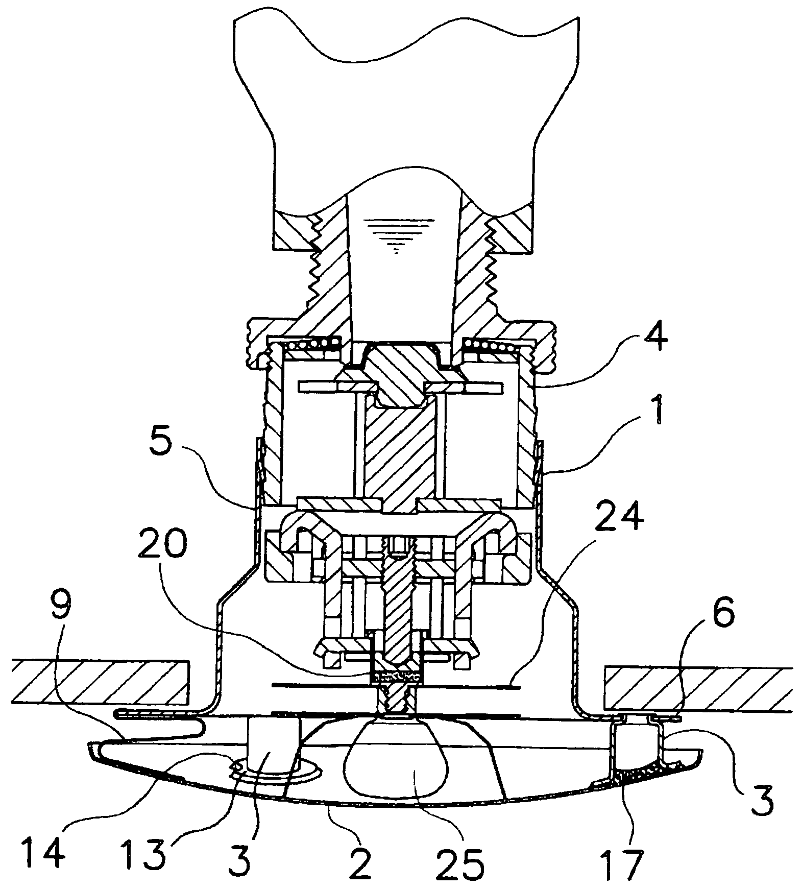
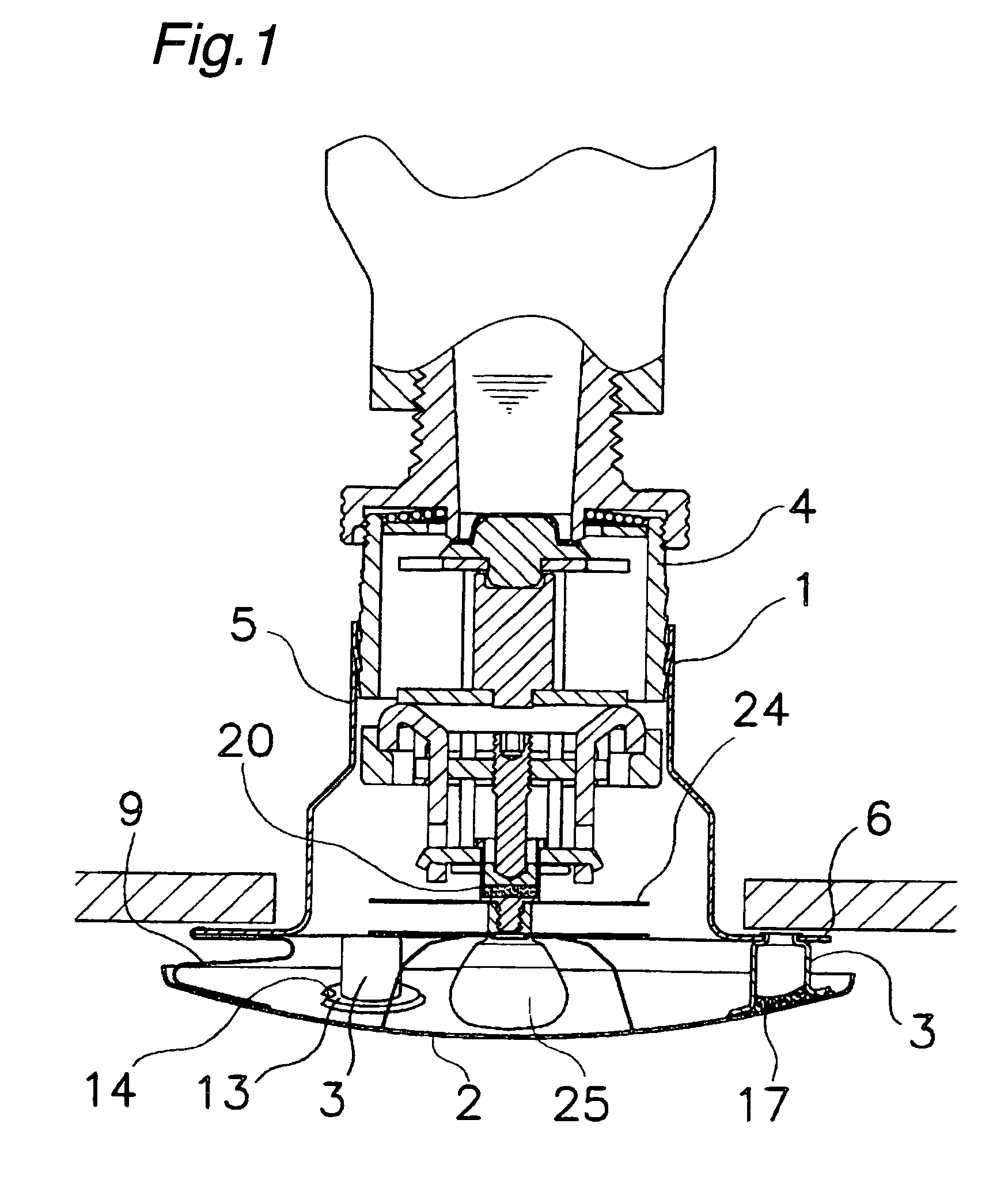
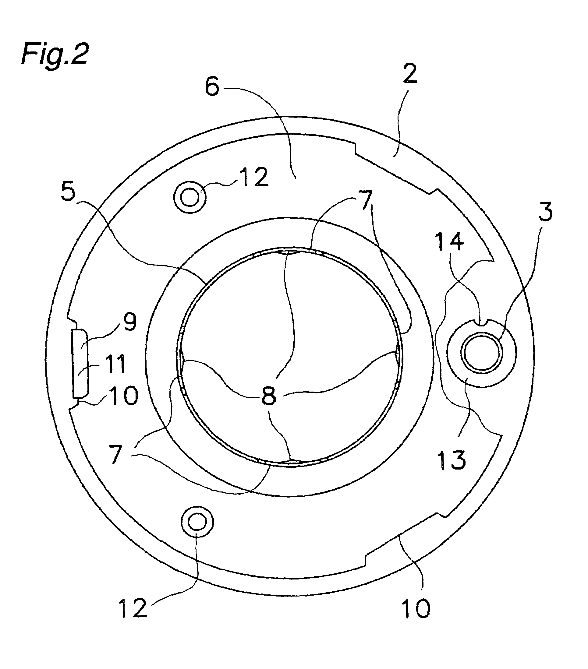
[0055]The first embodiment of the present invention will now be described with reference to FIGS. 1 to 7. FIG. 1 is a sectional view of a sprinkler head cover and a sprinkler head of the first embodiment. FIG. 2 is a plan view of the sprinkler head cover. FIG. 3 is an exploded sectional view of the sprinkler head cover. FIG. 4 is a sectional view of a cover plate and a mount before their having been connected to each other. FIG. 5 is a sectional view of the cover plate and the mount after their having been connected to each other. FIG. 6 is a sectional view of the sprinkler head. FIG. 7 is an enlarged sectional view of an engagement between the sprinkler head cover and the sprinkler head. FIG. 8 shows a state when the cover plate has dropped off; and FIG. 9 shows a state when the sprinkler head has been actuated.

[0056]The sprinkler head cover of the first embodiment, as shown in FIGS. 1 to 3, comprises a housing 1, a cover plate 2 and a mount 3 and the sprinkler head cover is attach...

embodiment 2

[0099]Subsequently, a second embodiment will now be described with reference to FIGS. 10 to 12. FIG. 10 is a sectional view of a sprinkler head cover and a sprinkler head of the second embodiment while FIG. 11 is a sectional view of a housing of the second embodiment. FIG. 12 is a plan view of a housing of the second embodiment.

[0100]The sprinkler head cover of the second embodiment comprises a housing 31 and a cover plate 2, and the cover is adapted to be attached to the sprinkler head 4. It is to be noted that the cover plate 2 and the sprinkler head 4, as they have structures similar to those in the first embodiment, are designated with the same reference numerals and any detailed description thereof is omitted herein. In addition, as to the housing 31, as well, the components and portions having the same structures and functions as those in the first embodiment are designated with the same reference numerals and any detailed description thereof is omitted herein.

[0101]The housin...


PUM


Abstract

A sprinkler head cover including a housing adapted to be attached to a sprinkler head which is connected to a water supply piping and in which, in the case of fire, a valve disposed inside the sprinkler head is opened to allow a fire-extinguishing liquid in the water supply piping to be dispersed. A cover plate is adapted to cover the sprinkler head so that the sprinkler head cannot be seen from outside, and a mount is installed in the housing and has a hole inside thereof. The cover plate and the mount are connected to each other by a low melting point alloy melted out from the hole, and a heat collector of the sprinkler head has a structure for allowing the heat collector to come into contact with the cover plate.

Description

BACKGROUND OF THE INVENTION[0001]1. Technical Field of the Invention[0002]The present invention relates to a sprinkler head to be installed in a building and actuated in case of fire to spread a fire-extinguishing liquid. The present invention also relates to a sprinkler head cover to be installed in the same sprinkler head.[0003]2. Description of Related Art[0004]A sprinkler head installed in a ceiling or a wall of a building interior is coupled to a water supply piping, in which a nozzle is closed by a valve within the sprinkler head. The valve is supported by a heat-sensitive operating section in which is incorporated a heat-sensitive element, and in operation, the heat-sensitive element can sense the heat from fire and trigger the heat-sensitive operating section to be actuated for opening the valve.[0005]When the valve is open, a fire-extinguishing liquid within the nozzle is released, and the fire-extinguishing liquid would impinge upon a deflector disposed ahead of the nozzle...

Claims


Application Information

Patent Timeline
Patent Type & Authority Patents(United States)
IPC IPC(8): A62C37/36A62C3/00A62C37/08B05B1/28B05B15/04A62C37/09A62C37/12
CPCA62C37/09A62C37/12A62C37/08
Inventor KOIWA, YASUAKI
Owner SENJU SPRINKLER
Why Eureka
Try Eureka