
Propelling system for boat

a propelling system and boat technology, applied in the field of propelling systems, can solve the problems of high water drag, damage to the boat, and the inability to use the inside space of the small boat b>1/b> around the middlebody or afterbody area for other purposes, and achieve the effect of increasing the usable internal space of the boa

Inactive Publication Date: 2009-06-09
SOLAS SCI & ENG
View PDF7 Cites 3 Cited by
  • Summary
  • Abstract
  • Description
  • Claims
  • Application Information

AI Technical Summary

Benefits of technology

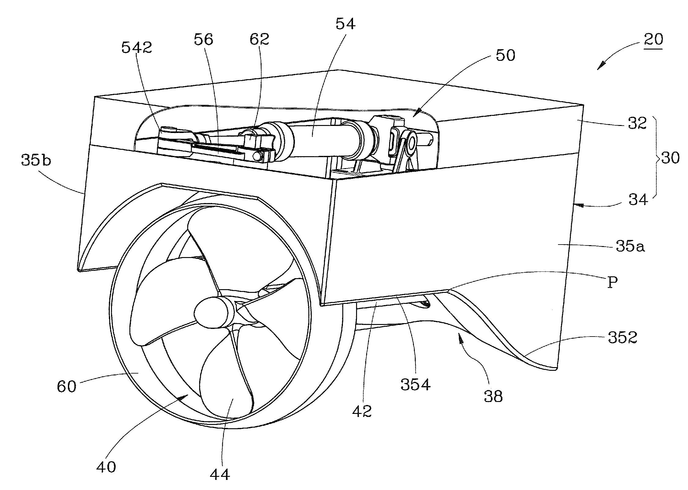
"The present invention provides a propelling system for a boat that can increase the usable internal space of the boat, change direction of the boat when it sails forward or backward, reduce water drag when the boat sails forward, and protect divers and the endangered species of marine fauna and flora from damage. The system includes a housing, a propeller, a driving device, and a guide ring. The housing is mounted on the stern of the boat and has a receiving chamber inside and a waterway at the bottom side. The propeller is rotatably disposed in the waterway of the housing. The driving device is mounted in the receiving chamber of the housing and has a driving member and a linking member pivotally coupled to the driving member. The guide ring is connected to the linking member of the driving device and located in the waterway of the housing in such a way that the guide ring surrounds blades of the propeller and is pivotally moveable relative to the propeller by the actuation of the driving member through the linking member. The technical effects of the invention include increasing the usable internal space of the boat, controlling the sailing direction of the boat, reducing water drag when the boat sails, and protecting divers and the endangered species of marine fauna and flora from damage."

Problems solved by technology

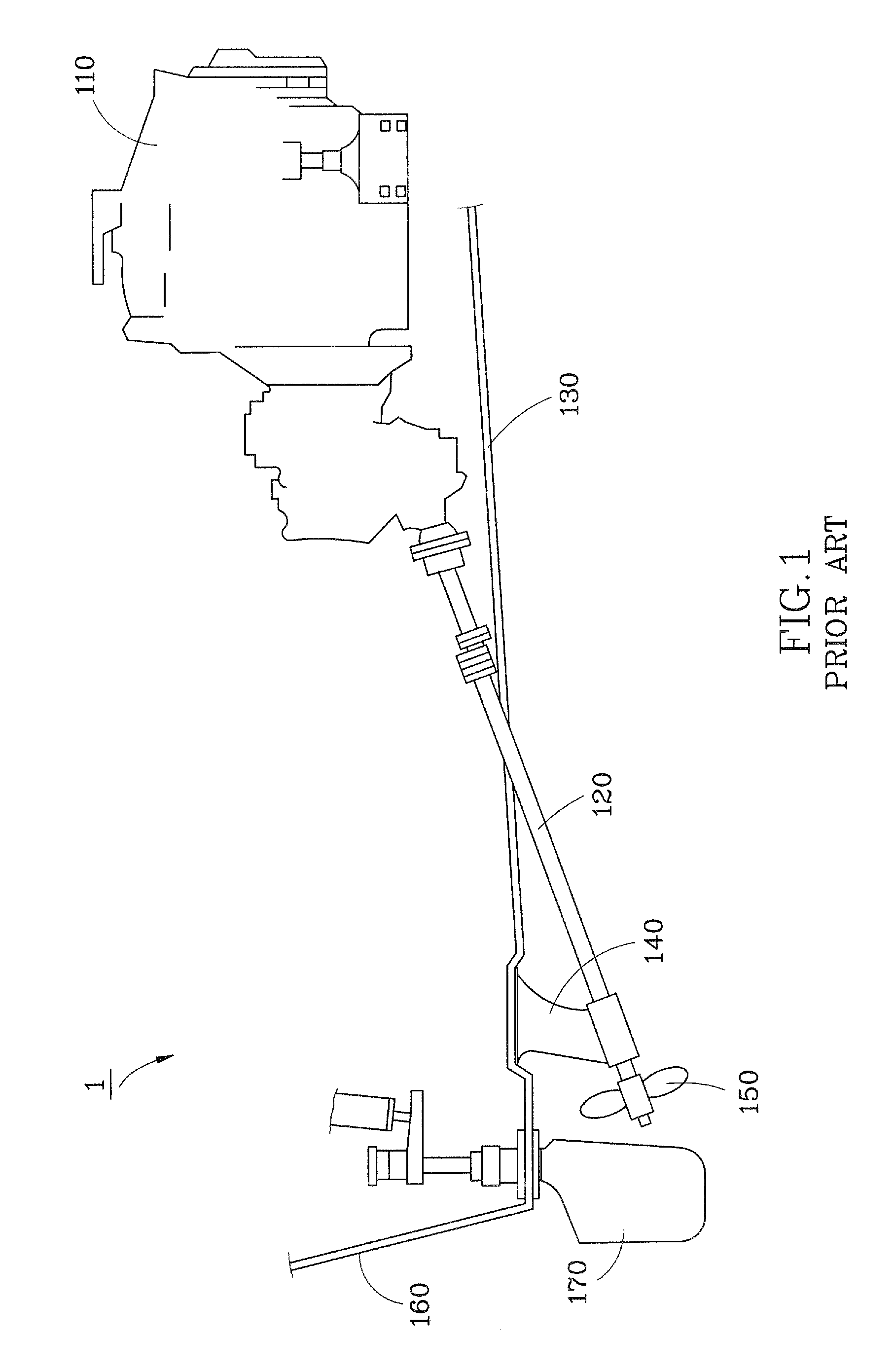
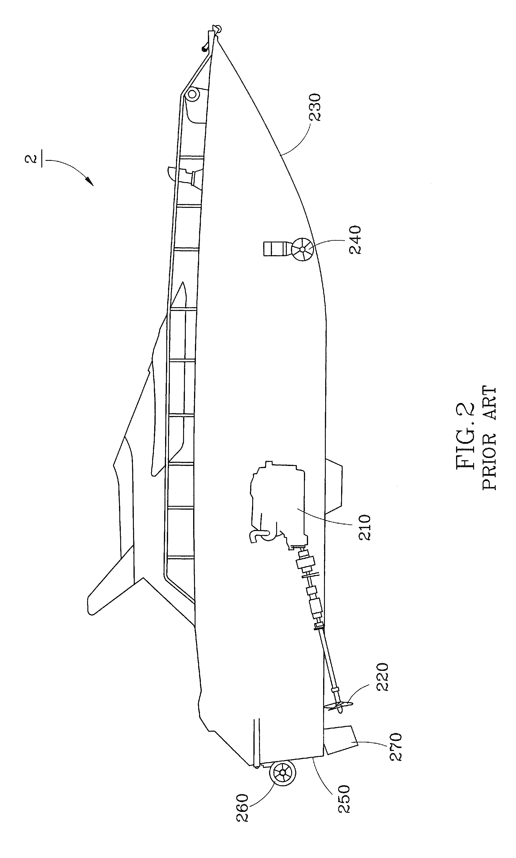
Because the A-shaped frame 140, the rudder 170 and the propeller 150 are located under the bottom 130 of the small boat 1, these components not only cause relatively higher water drag to reduce the speed of the small boat 1, but also tend to bump a rock or a driftwood accidentally, resulting in damage of themselves.
In addition, the engine 110 is generally mounted inside the small boat 1 at the middlebody or afterbody of the boat; therefore, the inside space of the small boat 1 around the middlebody or afterbody area may not be usable for other purpose, i.e. the usable inside space of the small boat 1 is restricted.

Method used


Image

  • Propelling system for boat
  • Propelling system for boat
  • Propelling system for boat

Examples


Embodiment Construction

[0029]Referring to FIG. 3 to FIG. 8, a propelling system 20 in accordance with a preferred embodiment of the present invention comprises a housing 30, a propeller 40, a hydraulic driving device 50 and a guide ring 60. As shown in FIG. 8, the propelling system 20 is installed in a small boat having a hull 10, an engine 12 mounted inside the hull 10 near a stem 14 of the hull 10 and a deck 16 fixed to the stern 14 of the hull 10.

[0030]The housing 30 has a front end thereof affixed to the stern 14 of the hull 10 of the small boat and is located under the deck 16 of the hull 10 of the small boat, as shown in FIG. 8. The housing 30 includes a base 34 and a lid 32 covered on a top side of the base 34 to define a receiving chamber 36 therebetween. The base 34 has two sidewalls 35a and 35b, each of which has a first section 352 extending slantingly from a front end of the base 34 to a position P located at the middle of the sidewalls 35a or 35b, and a second section 354 extending horizontal...


PUM


Abstract

A propeller system for a boat includes a housing adapted to be mounted to a stern of the boat and having a receiving chamber inside and waterway at the bottom side thereof, a propeller rotatably disposed in the waterway of the housing, a driving device mounted in the receiving chamber of the housing and having a driving member and a linking member pivotally coupled to the driving member, and a guide ring connected to the linking member of the driving device and located in the waterway of the housing in such a way that the guide ring surrounds the blades of the propeller and is pivotable relative to the propeller. Thus, the propelling system has the advantage of increasing the utilization of the internal space of the boat.

Description

BACKGROUND OF THE INVENTION[0001]1. Field of the Invention[0002]The present invention relates generally to a propelling system for use in a boat and more specifically, to a propelling system that can broaden the usable internal space of the boat.[0003]2. Description of the Related Art[0004]FIG. 1 is a schematic drawing showing a propelling system equipped in a small boat 1 according to prior art. The middlebody of hull of the small boat 1 is installed with an engine 110 to which a driving shaft 120 is connected. The driving shaft 120 slantingly downward penetrates through the bottom 130 of a small boat 1 and is supported by an A-shaped frame 140 and then coupled with a propeller 150. Further, the small boat 1 is provided at a stern 160 thereof with a rubber 170.[0005]Because the A-shaped frame 140, the rudder 170 and the propeller 150 are located under the bottom 130 of the small boat 1, these components not only cause relatively higher water drag to reduce the speed of the small bo...

Claims


Application Information

Patent Timeline
Patent Type & Authority Patents(United States)
IPC IPC(8): B63H5/16B63H25/06
CPCB63H5/125B63H21/30B63H25/48B63H2021/307
Inventor LIN, YEUN-JUNN
Owner SOLAS SCI & ENG
Learn More