Rotatable lead introducer

a lead introducer and rotatable technology, applied in the field of medical devices, can solve the problems of increasing fluoroscopy exposure, increasing the difficulty of electrophysiologists placing cs leads, and not clinically practicable lead placement to da

Active Publication Date: 2009-06-09
WILSON GREATBATCH LTD
View PDF16 Cites 628 Cited by
  • Summary
  • Abstract
  • Description
  • Claims
  • Application Information

AI Technical Summary

Benefits of technology

[0015]The adjustable angle used in the present invention allows for numerous real time adjustments when approaching the heart. Some devices according to the present invention include one remotely steerable surgical tool with a single hinge point that is capable of a maximum range of motion of approximately 95°. It can consist of an internal hinged “skeleton” that can be used to support steering and an external tube structure that is used to transmit torque to the helical fixation device on the lead. Some embodiments of the invention allow for single-handed operation by the implanter.

Problems solved by technology

Placement of a lead inside the left ventricle has not been clinically feasible to date due to dislodgement and the risk of embolism formation potentially leading to a stroke.
CS leads have been challenging for the electrophysiologist to place and often require considerably more time and increased fluoroscopy exposure than traditional endovascular right side leads.
Following implantation, the CS lead may dislodge in 10+% of patients leading to less than desirable performance.
The invasiveness of a full sternotomy would not be well tolerated by the CHF patients.
The placement of the lead on the apex of the heart is not desirable for resynchronization therapy.
This alignment is extremely challenging since the target spot is not directly visualized.
Many or most traditional lead introducers are not suited for a MI approach due to their size and need for a straight-line approach.

Method used


Image

  • Rotatable lead introducer
  • Rotatable lead introducer
  • Rotatable lead introducer

Examples


Embodiment Construction

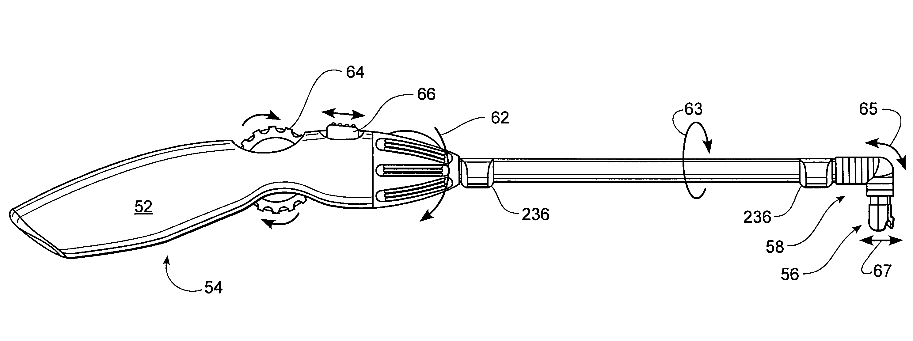
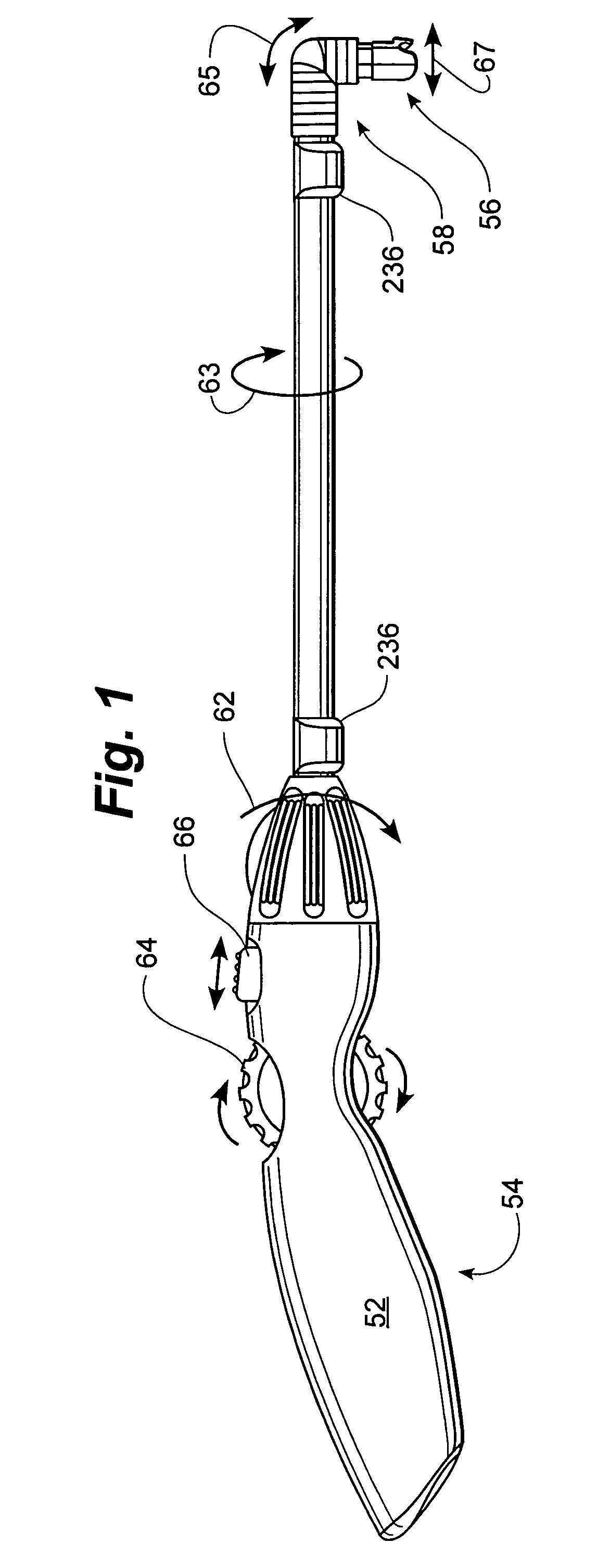
[0047]FIG. 1 illustrates a lead introducer 50 including a handle 52, a proximal portion 54, a distal portion 56, and a bendable portion 58. Introducer 50 further includes a rotation / torque knob or control 62, a steering or bending knob or control 64, and a release slider control 66. Knob 64 can be rotated to effect bending movement indicated at 65. Control 66 can be slid to effect head release indicated at 67. Knob 62 can be rotated to effect outer tube and collet rotation indicated at 63. Lead guides 236 may allow the lead to be rotatably carried with the rotating outer tube. The various elements introduced in FIG. 1 will be described in detail elsewhere.

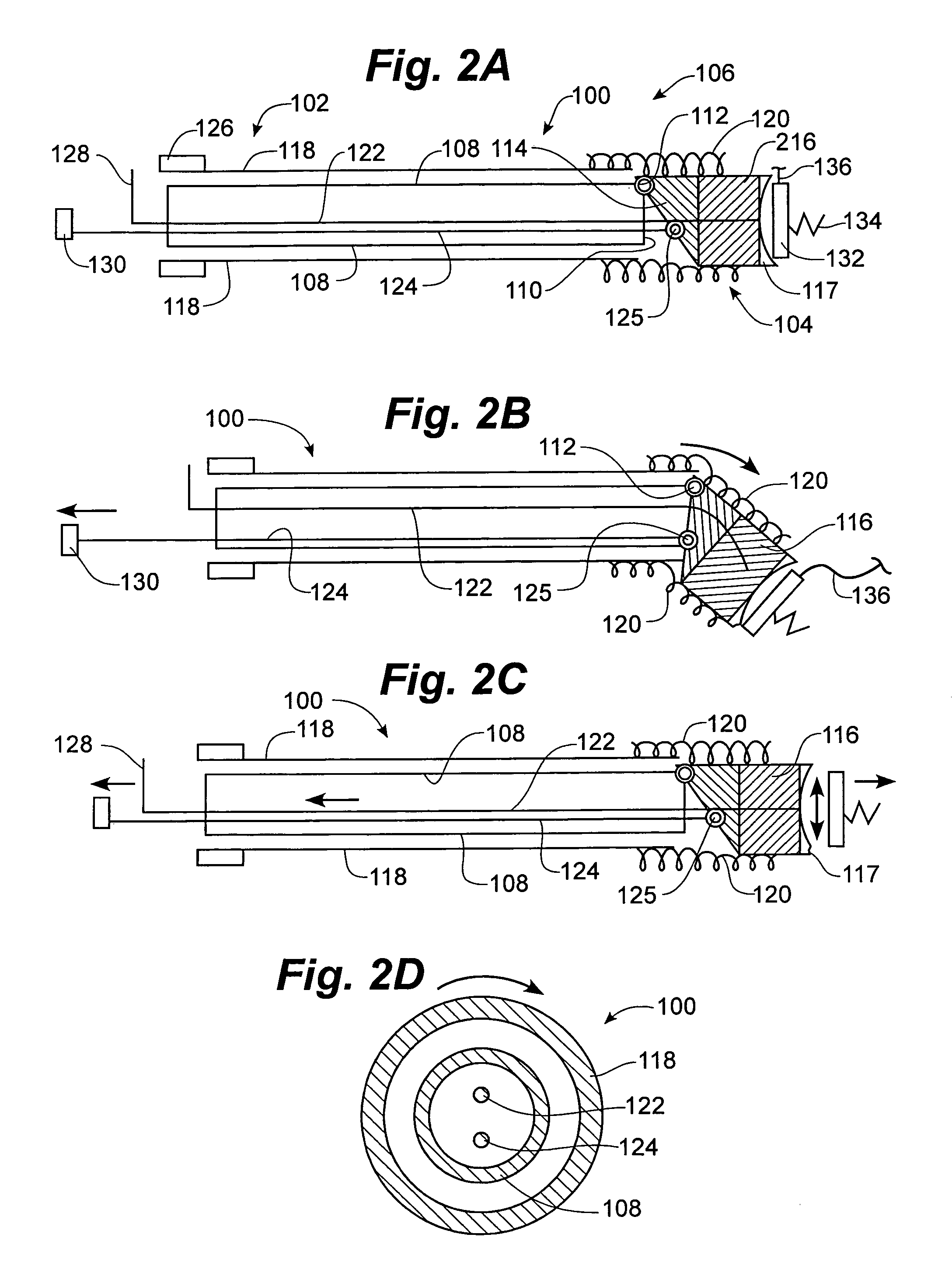
[0048]FIG. 2A illustrates a highly diagrammatic lead introducer 100 including a proximal portion 102, a distal portion 104, and a bendable portion 106. Lead introducer 100 includes an inner stem or stiffener 108 which may be a solid shaft or tube that does not rotate and may be fixedly secured to the handle in some embodiments. Int...


PUM


Abstract

Minimally invasive introducers and methods that can be used for rotationally securing devices within the human body. Introducers can include a distal element for releasably engaging a lead head controllable from a proximal control located outside of the body. An inner stem can extend between a proximal portion and a distal portion, and be pivotally and rotatably coupled to the distal lead engagement mechanism. An outer tube can be rotatably disposed over the inner stem and be flexibly coupled over the pivot to rotationally drive the distal element. A helical epicardial-myocardial lead electrode can be secured and oriented straight ahead and introduced through a port or small incision with the introducer in a straight configuration. The introducer can then be bent and rotated to screw the helical electrode into the heart.

Description

RELATED APPLICATIONS[0001]The present application is a non-provisional of U.S. Provisional Patent Application No. 60 / 468,352, filed May 6, 2003, titled LEAD INTRODUCER, herein incorporated by reference in its entirety.FIELD OF THE INVENTION[0002]The present invention is related generally to medical devices. More specifically, the present invention is related to minimally invasive medical instruments for securing devices within the human body. One example of use is securing an epicardial-myocardial pacing lead to the heart.BACKGROUND OF THE INVENTION[0003]Several major CRM companies have developed special pacemakers “IPGs” that allow for the delivery of resynchronization therapy. This technology uses atrial synchronized, biventricular pacing and requires placement of a lead in or on the right atrium as well as the right and left ventricles. Placement of a lead inside the left ventricle has not been clinically feasible to date due to dislodgement and the risk of embolism formation pot...

Claims


Application Information

Patent Timeline
Patent Type & Authority Patents(United States)
IPC IPC(8): A61B19/00A61N1/00A61B17/00A61B17/04A61B17/28A61B17/88A61N1/05
CPCA61B17/8888B25B27/143A61N1/0587A61B2017/00243A61B2017/003A61B2017/0409A61B2017/2929A61N2001/0578A61B2017/0441A61B2017/2937
Inventor KELSCH, DANIEL N.MELLOR, JAMES L.RUNDLE, KENNETH P.FELL, ROGER B.JAHNS, SCOTT E.ERICKSON, DAVE S.FISCHER, III, VINCENT A.ANDERSON, KENT D.
Owner WILSON GREATBATCH LTD
Why Eureka
Try Eureka