Valve and process for interrupted continuous flow chromatography

a continuous flow and chromatography technology, applied in the field of continuous flow chromatography, can solve the problems of reducing the friction coefficient and correspondingly the wear area of the moving parts, and achieve the effect of reducing the friction coefficient and correspondingly the wear area

Active Publication Date: 2009-06-09
SEMBA
View PDF94 Cites 27 Cited by
  • Summary
  • Abstract
  • Description
  • Claims
  • Application Information

AI Technical Summary

Benefits of technology

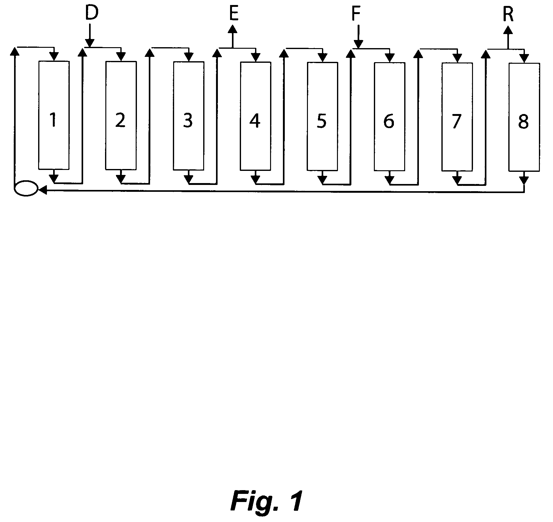
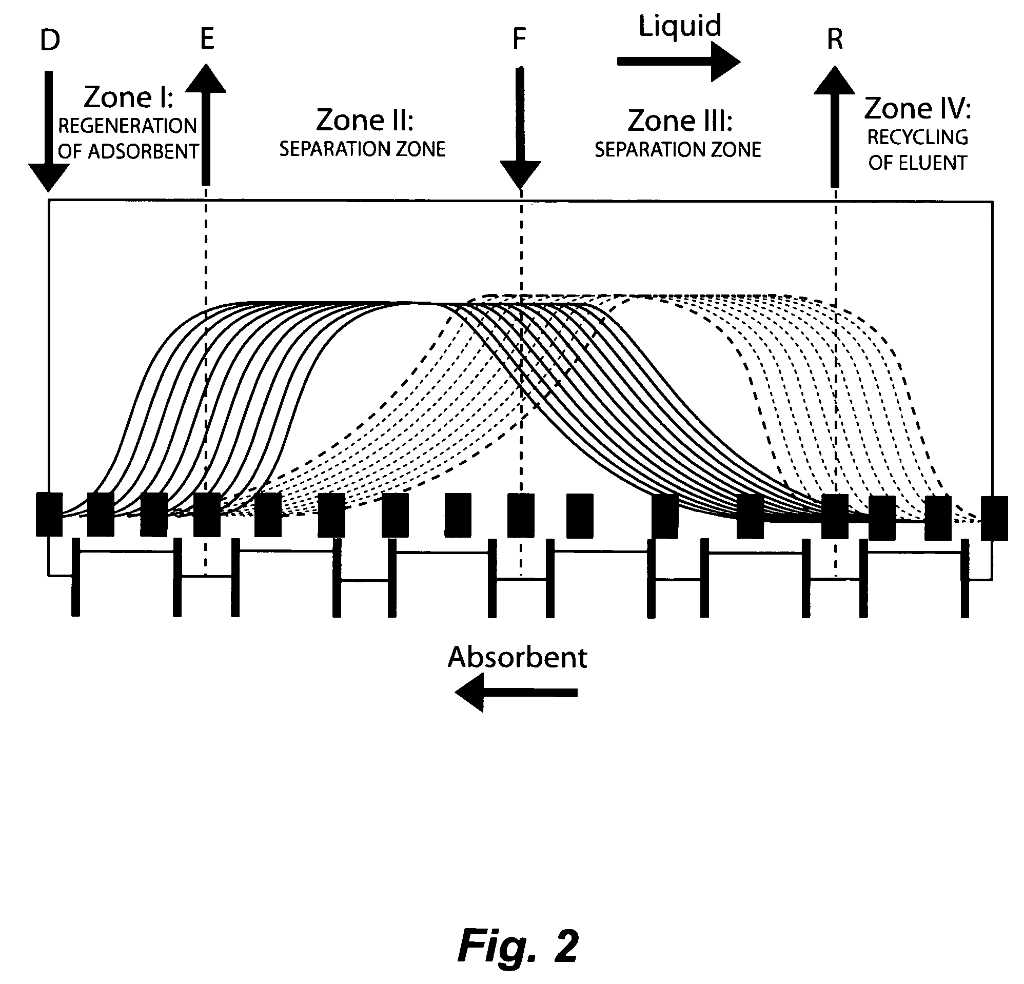
[0014]Most simulated moving bed (SMB) chromatography systems are designed for large scale industrial applications involving thousands of gallons of feedstock, and tons of final product. Flow in such systems is highly constrained because of the necessity of maintaining continuous flow of large volumes of liquid in each stage of the process. Small scale systems are not nearly so constrained in part because perturbations in flow are more readily tolerated when circulating flow volume is small compared to bed volume in the columns. It is therefore an object of the present invention to interrupt flow in the series at critical points where inflows and outflows from the system to prevent any possible unintended contamination of columns adjacent to the points of fluid ingress or egress, as will become apparent hereafter.
[0015]The key to efficiency of SMB in which each column in the series alternately performs a succession of chromatographic functions, is the valving system. The multi-port rotary valve of the present invention is designed for simplicity of construction, ease of assembly and disassembly, and minimization of wear on the moving parts. In one embodiment, the present valve comprises three substantially flat plates, and in a second embodiment four such plates, maintained in alignment. The bottom plate and a rigid plate composed of a fluorocarbon polymer attached to it are mounted on a frame or carousel, and rotate against an interfacing plate. Each of these structures has a plurality of bores arranged in two concentric arrays of equal number corresponding to the number of potential liquid flows with each outflow from one column connected to only one inflow of the next column in succession. The rigid plate has a lapped surface to a flatness tolerance of not greater than 15 microns, and preferably 1-3 microns, and can readily withstand up to 500 psi and 500 ft. lb of torque. All of the bore arrays are arranged to be in unobstructed alignment when the valve components are layered together. Means are provided to apply uniform pressure across the plates so as to attain a hydraulic seal able to withstand pressures of up to 200 psi.
[0016]The stationary interfacing plate similarly has two concentric arrays of bores corresponding in alignment to the bores of the first and rigid plates. The outer portions of these bores are partially threaded to receive connectors for attachment of cross-over conduits interconnecting one column to the next in the series. On the undersurface of the interfacing plate each array of bores is surrounded by a continuous concentric recess whose cavities are designed to receive a fabric entrained gasket. The gasket has holes corresponding to the position and size of the bores in the recess that receives it. The gasket is further made of material thicker than the depth of the recesses, so that when the valve components are assembled, the gasket provides not only sealing engagement between the rigid plate and the interfacing plate, but also reduces the coefficient of friction, and correspondingly the area of wear on the moving parts. It is also advantageous that the gasket is held in place mechanically without use of any chemical adhesive, to facilitate periodic replacement.
[0020]An upper support plate is joined to the plurality of outer pillars and has a central aperture and bearing means to receive the upper most portion of the central shaft rising vertically from the inner frame base plate. The purpose of the outer frame is to maintain vertical alignment of the shaft and provide overall lateral stability. The central shaft is further characterized in having threads in the portion of shaft between the interfacing plate of the valve assembly and the outer support frame plate, Pressure sufficient to achieve sealing engagement of the valve components is obtained by exerting pressure on the interfacing plate of the valve by compressing a spring disposed between the interfacing plate and a threaded push plate held in place by a lock nut.
[0022]The method of the present invention can be used in any SMB of generic construction, in which the volume of liquid flow in the system is small enough not to result in large pressure spikes and depressions, or result in other fluid effects such as water hammer, rupture of conduits and fittings, and the like when interrupted at one or more points in the circulation loop for the time a columns remain in one index position. According to the method, flow is interrupted by interrupting means to any one of two positions occurring in a column immediately downstream from either or both of the inflows of feedstock or desorbent, and optionally interrupting the flow to columns upstream of the outflows of raffinate or extract. In practice, such interruption of flow prevents cross-contamination of columns adjacent to inlets and outlets, thereby sharpening the peaks of separation and optimizing recoveries of product. It is especially adaptable to very small SMB systems useful in drug discovery and separation of highly structurally related chemical compounds.

Problems solved by technology

The gasket is further made of material thicker than the depth of the recesses, so that when the valve components are assembled, the gasket provides not only sealing engagement between the rigid plate and the interfacing plate, but also reduces the coefficient of friction, and correspondingly the area of wear on the moving parts.

Method used


Image

  • Valve and process for interrupted continuous flow chromatography
  • Valve and process for interrupted continuous flow chromatography
  • Valve and process for interrupted continuous flow chromatography

Examples


example

[0060]Experiments were conducted on a high fructose feedstock to measure separation efficiency of fructose and glucose utilizing an SMB chromatography as heretofore disclosed in the first embodiment. Sixteen columns containing approx. 150 cubic centimeters of packed Dowex Monosphere 99CA / 320 ion exchange resin (Supelco) were installed in the machine, and allowed to equilibrate. Identification and quantitation of sugars in the extract and raffinate were carried out by HPLC on an HP 1090 liquid chromatograph, calibrated with pure glucose and fructose, under the following conditions: detection at 192 nm, HPLC column type Hypersil APS 5 micrometers, 150 mm×4.6 mm. The samples were diluted in water, acetonitrile in a 75:25 ratio. The mobile phase was 20:80 water-acetonitrile. The results are shown in FIG. 10a.

[0061]High concentration fructose (Archer Daniels, Midland No. 42) was introduced into the system as feedstock. The feed rate thereof and the desorbent rate were kept constant, and...


PUM

PropertyMeasurementUnit
flatnessaaaaaaaaaa
flatnessaaaaaaaaaa
flatnessaaaaaaaaaa

Abstract

A unique valve assembly for simulated bed moving chromatography employs a combination of pressure compatible sealable materials that permit minimal frictional interaction between moving parts, ensures alignment of parts, and provides a method for conducting SMB countercurrent chromatography on a small scale, in which purity and separation efficiency are enhanced. Machine designs are disclosed which embody the SMB concepts. Finally, a quick disconnect connector and adaptor is provided for mounting chromatographic columns in an SMB device. Demonstration of this system in a fructose-glucose isomer separation with purity-recovery trade-off for this device is also presented.

Description

FIELD OF THE INVENTION[0001]The present invention relates generally to continuous flow chromatography, and more particularly, to Simulated Moving Bed (SMB) chromatography. The invention provides a novel strategy for small scale separations of liquid components in a stream, and a simplified valve design for directing liquids to appropriate destinations within the system.BACKGROUND OF THE INVENTION[0002]In typical solid phase chromatography processes, a solution containing a mixture of substances is passed through a bed of adsorbent. One or more of the dissolved substances in the flow has a greater tendency to be adsorbed onto the solid matrix than others. In the case of gel filtration separation is based on molecular weight, with small substances permeating the gel which retards their movement through the gel relative to larger molecules which are excluded from the pores of the gel. In ion exchange chromatography, the principle of separation involves differential interaction with a r...

Claims


Application Information

Patent Timeline
Patent Type & Authority Patents(United States)
IPC IPC(8): B01D15/08
CPCF16K11/074G01N30/20B01D15/1821G01N30/461G01N30/6047G01N2030/201G01N2030/202Y10T137/86815
Inventor OROSKAR, ANIL RAJARAMPARIKH, SAURABH PARESHOROSKAR, ASHA ANILJOHNSON, KENNETH U.ESCARCEGA, ANTHONY JOSEPH
Owner SEMBA
Why Eureka
Try Eureka