Leakage current compensated system

a leakage current compensation and leakage current technology, applied in electronic switching, pulse technique, instruments, etc., can solve problems such as the shape of deformable mirrors, and achieve the effects of improving leakage current compensation, reducing refresh rate, and reducing refresh ra

Active Publication Date: 2009-06-09
NORTHROP GRUMMAN SYST CORP
View PDF18 Cites 6 Cited by
  • Summary
  • Abstract
  • Description
  • Claims
  • Application Information

AI Technical Summary

Benefits of technology

[0007]It is a further object of this invention to provide such an improved leakage current compensation circuit which requires a lower refresh rate.
[0008]It is a further object of this invention to provide such an improved leakage current compensation circuit in which more channels can be addressed per drive amplifier because of the lower refresh rate.
[0009]It is a further object of this invention to provide such an improved leakage current compensation circuit which requires less power, cost, and space per channel because fewer drive amplifiers are required.
[0010]The invention results from the realization that an improved leakage current compensation circuit for a multiplex driver system which requires lower refresh rate, lower space, power and cost and can be achieved with a multichannel mux having a predetermined leakage current at the switched side of each channel and a leakage current compensation circuit associated with the switched side of each channel for providing a compensation current matched to the predetermined leakage current.
[0014]The invention also features a leakage current compensated multiplex drive system for a deformable mirror including a drive amplifier for providing address synchronize inputs for each actuator of a deformable mirror. There is a multichannel mux for selectively applying the inputs to the addressed actuators. The multichannel mux has a predetermined leakage current at the switched side of each channel. A leakage current compensation circuit associated with the switched side of each channel provides a compensation current matched to the predetermined leakage current for reducing charge loss from the actuators.

Problems solved by technology

However, some leakage occurs through the open channels of the power mux so that the proper charge / voltage is not maintained on the actuators and the shape of the deformable mirror is compromised.

Method used


Image

  • Leakage current compensated system
  • Leakage current compensated system
  • Leakage current compensated system

Examples


Embodiment Construction

[0023]Aside from the preferred embodiment or embodiments disclosed below, this invention is capable of other embodiments and of being practiced or being carried out in various ways. Thus, it is to be understood that the invention is not limited in its application to the details of construction and the arrangements of components set forth in the following description or illustrated in the drawings. If only one embodiment is described herein, the claims hereof are not to be limited to that embodiment. Moreover, the claims hereof are not to be read restrictively unless there is clear and convincing evidence manifesting a certain exclusion, restriction, or disclaimer.

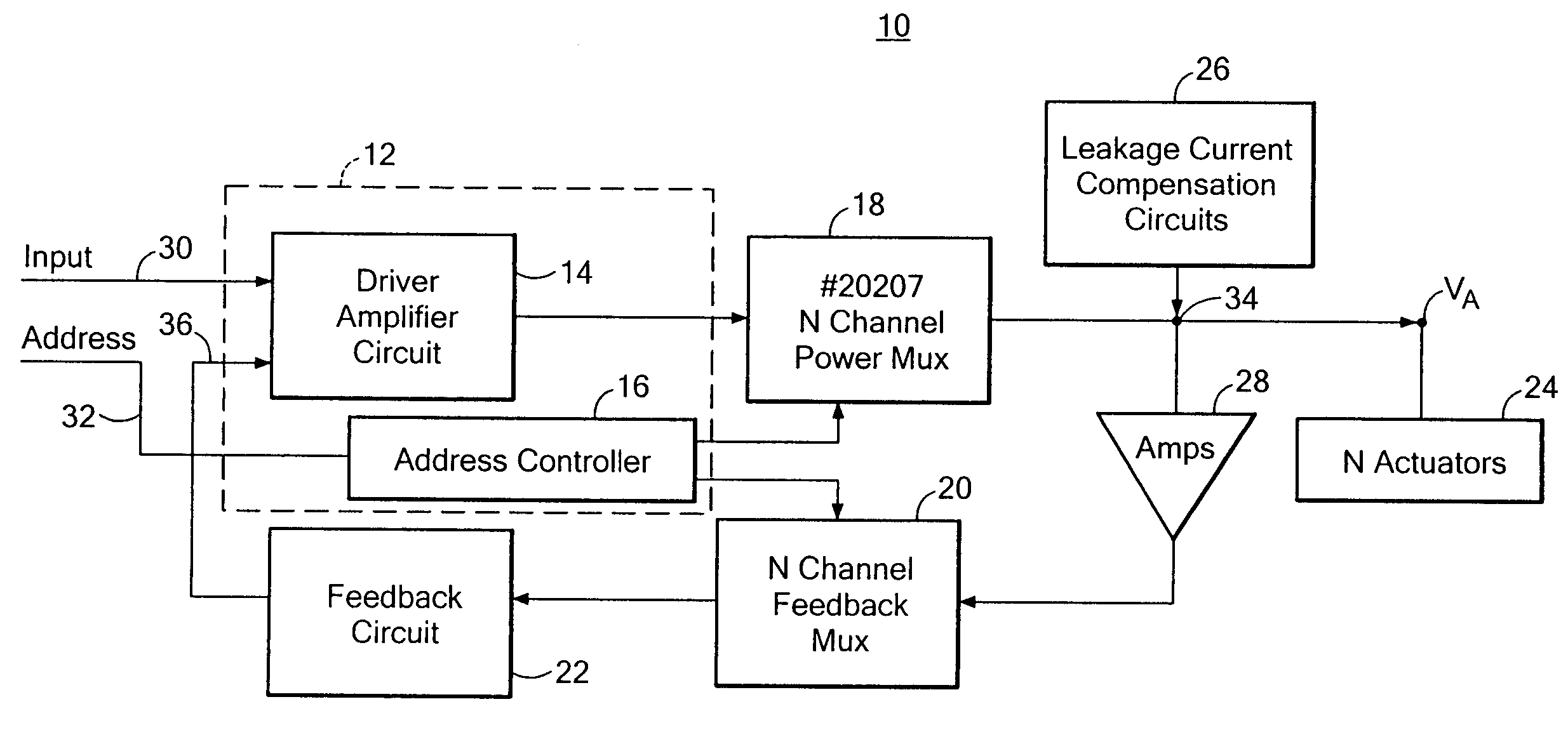
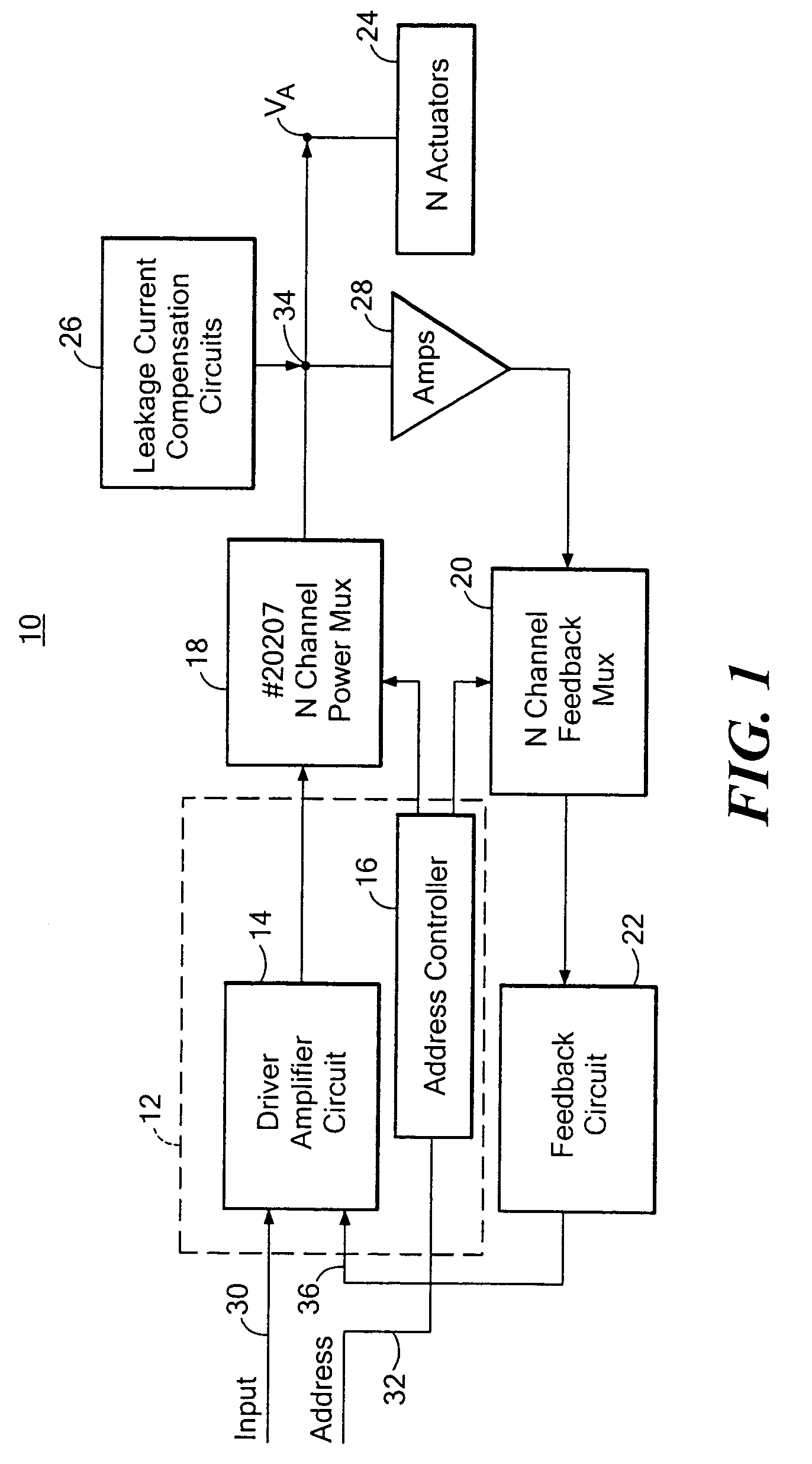
[0024]There is shown in FIG. 1 a leakage current compensated multiplex driver system 10 including a drive amplifier 12 having a drive amplifier circuit 14 and address controller 16. System 10 also includes an N channel power mux 18, N channel feedback mux 20, feedback circuit 22, and N actuators 24. Associated with each act...


PUM


Abstract

A leakage current compensated multiplex driver system includes a multichannel mux having a predetermined leakage current at the switched side of each channel and a leakage current compensation circuit associated with the switched side of each channel for providing a compensation current matched to the predetermined leakage current.

Description

FIELD OF THE INVENTION[0001]This invention relates to a leakage current compensation circuit for a mux and more particularly to such a leakage current compensation circuit in a multiplex driver system such as for driving actuators of a deformable mirror.BACKGROUND OF THE INVENTION[0002]Analog driver controls used, for example, to operate the actuators of deformable mirrors use a drive amplifier with a feedback circuit to provide the required voltage to the actuators. There may be N addressable actuators. An input signal address—synchronized with a particular actuator is delivered by the drive amplifier through an N-channel power mux which applies that input signal to the addressed one of N actuators. A feedback mux simultaneously synchronizes the switching of the feedback circuit with the addressable actuator. A typical mux is one such as a Model No. 20207 available form Supertex of Sunnyvale, Calif.[0003]Ideally each actuator will hold its charge as established by the input provide...

Claims


Application Information

Patent Timeline
Patent Type & Authority Patents(United States)
IPC IPC(8): G11C5/14
CPCH03K17/002H03K17/145H03K17/693
Inventor KREDA, EUGENE J.
Owner NORTHROP GRUMMAN SYST CORP
Why Eureka
Try Eureka