Array antenna calibration apparatus and method

a technology of array antennas and calibration methods, applied in electrical devices, instruments, antennas, etc., can solve the problems of limited channel capacity and inability to correctly control beam patterns, and achieve accurate results, reduce manufacturing costs, and ensure the interval-dependent calibration of antenna elements

Inactive Publication Date: 2009-06-09
FUJITSU LTD
View PDF14 Cites 79 Cited by
  • Summary
  • Abstract
  • Description
  • Claims
  • Application Information

AI Technical Summary

Benefits of technology

[0025]According to the present invention, for both a downlink and an uplink, antenna elements (e.g., dummy antennas) disposed, one on each side of antenna elements that are to be subjected to calibration, are used for transceiving calibration signals, thereby realizing accurate, antenna element interval-independent calibration. Accordingly, antenna element interval deviation is allowed, and array antenna yields are reduced, thereby contributing to reduction of the manufacturing cost.

Problems solved by technology

In CDMA, signal interference of other channels used in simultaneous communication causes a problem of a limited number of channels available in simultaneous communication, thereby causing a limited channel capacity.
That is, the adaptive array antenna forms a beam in the direction of the desired user, and it directs a null point in the direction of the user who becomes a significant source of interference.
Thus, phase variation in each radio unit will make it impossible to correctly control beam patterns.

Method used


Image

  • Array antenna calibration apparatus and method
  • Array antenna calibration apparatus and method
  • Array antenna calibration apparatus and method

Examples


first embodiment

[1] First Embodiment

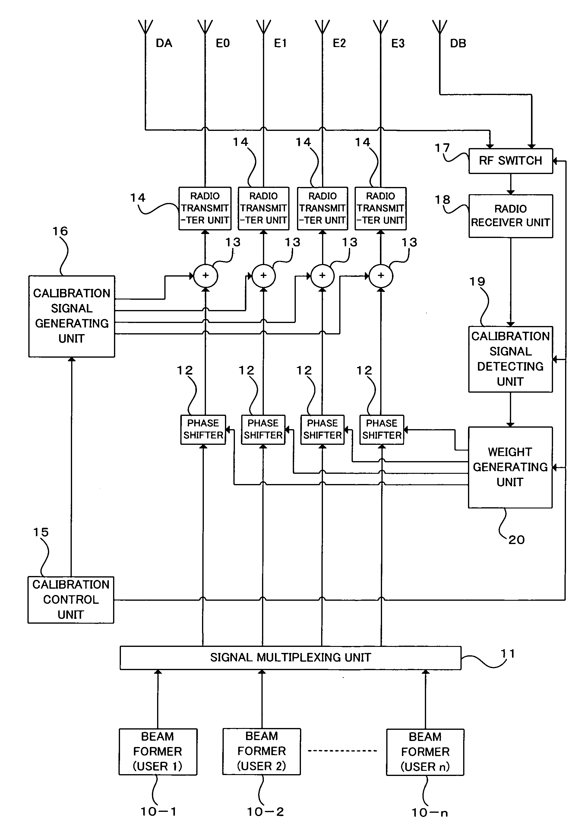
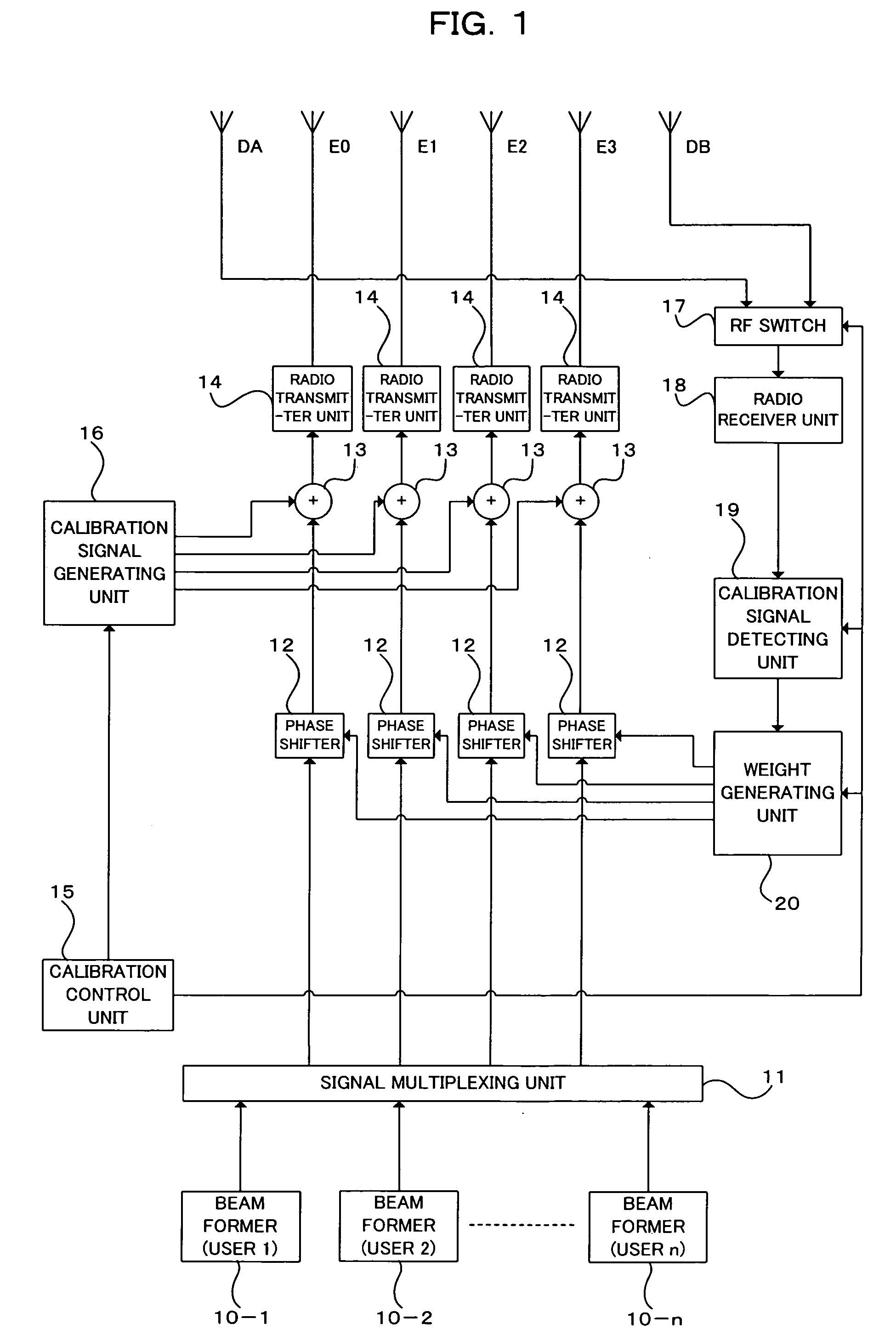
[0036]FIG. 1 is a block diagram showing a construction (for downlink) of a radio transmitter to which an array antenna calibration apparatus of a first embodiment of the present invention is applied. The radio transmitter of FIG. 1 includes: antenna elements E0, E1, E2, E3, DA, and DB (in FIG. 1, a total of six antenna elements) constituting a linear array antenna; beam formers 10-1 through 10-n (n is an integer not smaller than 2) for multiple users; a signal multiplexing unit 11; phase shifters 12, adders 13, and radio transmitter units 14 provided, one for each of the antenna elements E0, E1, E2, and E3; a calibration control unit 15; a calibration signal generating unit 16; an RF switch 17; a radio receiver unit 18; a calibration signal detecting unit 19; a weight generating unit 20. Antenna elements DA and DB disposed, one on each side of the linear array antenna, are dummy antennas for shaping emission patterns from the antenna elements E0, E1, E2, and E3. ...

second embodiment

[2] Second Embodiment

[0066]FIG. 3 is a block diagram showing a construction (for uplink) of a radio receiver to which an array antenna calibration apparatus of a second embodiment of the present invention is applied. The radio receiver of FIG. 3 includes: antenna elements E0, E1, E2, E3, DA, and DB (in FIG. 3, a total of six antenna elements) constituting a linear array antenna; radio receivers 31 and phase shifters 32 provided, one for each of the antenna elements E0, E1, E2, and E3; a signal demultiplexing unit 33; beam formers 34-1 through 34-n (n is an integer not smaller than 2) for multiple users; a calibration control unit 35; a calibration signal generating unit 36; a radio transmitter unit 37; an RF switch 38; a calibration signal detecting unit 39; and a weight generating unit 40. In this example, also, antenna elements DA and DB, disposed one on each side of the linear array antenna, are dummy antennas for shaping emission patterns from the antenna elements E0, E1, E2, an...

third embodiment

[3] Third Embodiment

[0090]FIG. 5 is a block diagram showing a construction (for downlink) of a radio transmitter to which an array antenna calibration apparatus of a third embodiment of the present invention is applied. The radio transmitter of FIG. 5 differs from the construction of FIG. 1 in that radio receiver units 18A and 18B and calibration signal detecting units 19A and 19B are provided for the dummy antenna elements DA and DB, respectively, instead of the RF switch 17.

[0091]Here, the radio receiver units 18A and 18B per se have the same or the similar functions to those of the radio receiver unit 18 already described. The calibration signal detecting units 19A and 19B per se have functions the same as or similar to those of the calibration signal detecting unit 19 already described. That is, although the construction of FIG. 1 includes one radio receiver unit 18 and one calibration signal detecting unit 19 for common use between the dummy antenna elements DA and DB by a swit...


PUM


Abstract

The apparatus comprises a calibration signal supply means, which supplies calibration signals to a plurality of antenna elements that are to be subjected to calibration; a calibration signal extracting means, which extracts the calibration signals from signals received by the antenna elements placed, one on each side of the plurality of antenna elements that are to be subjected to calibration, and a calibration control means and which individually controls the phases of signals to be transmitted from the plurality of antenna elements that are to be subjected to calibration, based on the phase differences among the calibration signals extracted by the calibration signal extracting means. This will realize accurate calibration of an array antenna, irrespective of antenna element interval deviation.

Description

CROSS REFERENCE TO RELATED APPLICATIONS[0001]This application is based on and hereby claims priority to Japanese Application No. 2005-147249 filed on May 19, 2005 in Japan, the contents of which are hereby incorporated by reference.BACKGROUND OF THE INVENTION[0002](1) Field of the Invention[0003]The present invention relates to an array antenna calibration apparatus and an array antenna calibration method. The invention relates particularly to a technique for calibrating phase differences at array antenna ends.[0004](2) Description of the Related Art[0005]Digital cellular radio communication systems employing the DS-CDMA (Direct Spread Code Division Multiple Access) technology have been developed as next-generation mobile communication systems. The CDMA scheme is an access scheme in which channels are assigned according to codes to make simultaneous communication available. In CDMA, signal interference of other channels used in simultaneous communication causes a problem of a limite...

Claims


Application Information

Patent Timeline
Patent Type & Authority Patents(United States)
IPC IPC(8): H01Q3/00
CPCH01Q3/267
Inventor KAWASAKI, TOSHIO
Owner FUJITSU LTD
Why Eureka
Try Eureka