Foot roll rigging

a technology of rigging and feet, applied in the field of computer graphics, can solve the problems of kinematic complexity, difficulty in creating walk animations, and difficulty in convincing walk animations with appropriate emotional expression and level of energy, and achieve the effect of efficient specification of the position and rotation of the

Active Publication Date: 2009-06-09
PIXAR ANIMATION
View PDF3 Cites 11 Cited by
  • Summary
  • Abstract
  • Description
  • Claims
  • Application Information

AI Technical Summary

Benefits of technology

[0009]An embodiment of the invention includes a system and method that enables animators to efficiently specify the positions and rotations of the feet of character models. In an embodiment, an animator specifies an initial foot model position. The initial foot model position specifies a foot model contact point. Animators specify one or more foot roll parameters that change the relative angle between at least a portion of the foot model and an initial orientation of an alignment plane. Foot roll parameters specify the rotation of the foot model around foot model contact points. Foot roll parameters can include heel roll, ball roll, and toe roll, which specify the rotation of the foot model around contact points on the heel, ball, and toe, respectively, of a foot model. To maintain the position of the foot model contact point, the foot model position is adjusted based on the foot roll parameter. The repositioned foot model is realigned with alignment plane, which restores contact at the foot model contact point.

Problems solved by technology

However, creating convincing walk animations with the appropriate emotional expression and level of energy is particularly challenging and time consuming.
One of the difficulties in creating walk animations arises from the kinematic complexity of walking itself.
Many animation tools make it difficult to mimic these kinematic attributes of walking.
Additionally, these rotations can also cause the foot to lift off the ground plane prematurely, or to penetrate below the ground plane.

Method used


Image

  • Foot roll rigging
  • Foot roll rigging
  • Foot roll rigging

Examples


Embodiment Construction

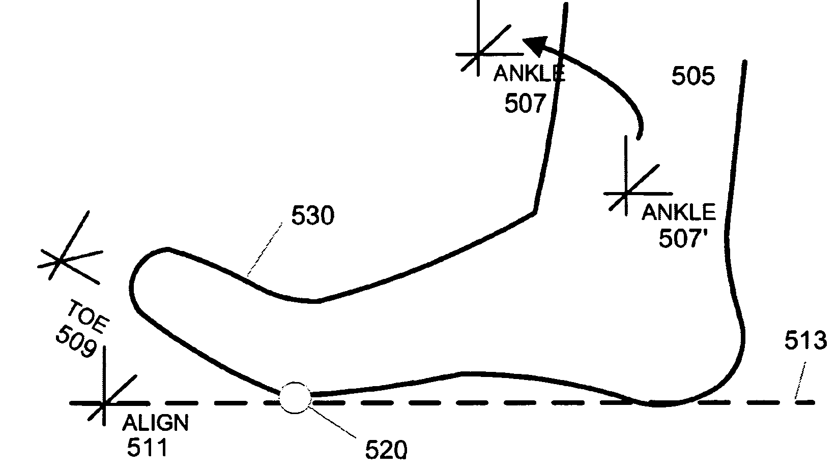
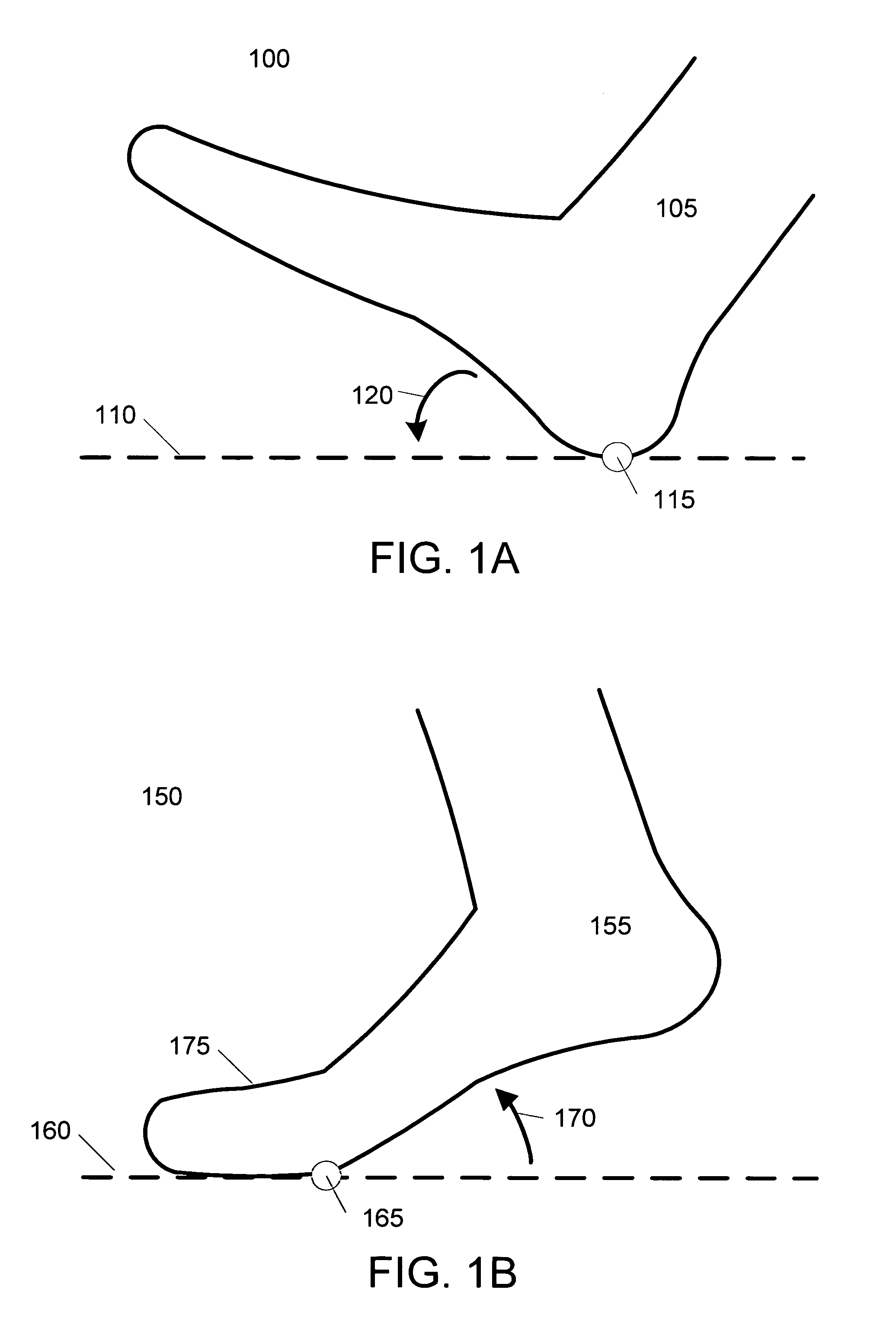
[0021]FIGS. 1A-1B illustrate two different phases of a walk animation suitable for an application of an embodiment of the invention. FIG. 1A illustrates a first phase 100 of a typical walk animation. In phase 100, the foot 105 of a character model contacts the ground plane 110 at heel contact point 115. As the character model moves forward, the foot 105 rotates around the heel contact point 115 until it is flat against the ground surface. The rotation 120 of the foot 105 around heel contact point 115 is referred to as heel roll.

[0022]FIG. 1B illustrates a second phase 150 of a typical walk animation. In phase 150, the foot 155 of a character model is lifted from the ground plane 160. In phase 150, the foot 155 rotates around ball contact point 165. Additionally, the toe portion 175 of the foot 155 bends so as to remain in contact with the ground plane 160. The rotation 170 of foot 155 around ball contact point 165 is referred to as ball roll.

[0023]Phases 100 and 150 are provided for...


PUM


Abstract

A system and method enables animators to pose character models' feet. An initial foot model position is received. The initial foot model position specifies a foot model contact point. One or more foot roll parameters are specified that change the relative angle between at least a portion of the foot model and an initial orientation of an alignment plane. Foot roll parameters specify the rotation of the foot model around foot model contact points. Foot roll parameters can include heel roll, ball roll, and toe roll, which specify the rotation of the foot model around contact points on the heel, ball, and toe, respectively, of a foot model. To maintain the position of the foot model contact point, the foot model position is adjusted based on the foot roll parameter. The repositioned foot model is realigned with alignment plane, which restores contact at the foot model contact point.

Description

CROSS-REFERENCES TO RELATED APPLICATIONS[0001]This application claims priority to U.S. Provisional Patent Application No. 60 / 572,008, filed May 17, 2004, which is incorporated by reference herein for all purposes.BACKGROUND OF THE INVENTION[0002]The present invention relates to the field of computer graphics, and in particular to methods and apparatus for animating computer generated characters. Many computer graphic images are created by mathematically modeling the interaction of light with a three dimensional scene from a given viewpoint. This process, called rendering, generates a two-dimensional image of the scene from the given viewpoint, and is analogous to taking a photograph of a real-world scene. Animated sequences can be created by rendering a sequence of images of a scene as the scene is gradually changed over time. A great deal of effort has been devoted to making realistic looking rendered images and animations.[0003]Animation, whether hand-drawn or computer generated, ...

Claims


Application Information

Patent Timeline
Patent Type & Authority Patents(United States)
IPC IPC(8): G06T15/70G06T13/00
CPCG06T13/40
Inventor RUSS, ROBERT HHOFFMAN, CHRISTIAN DMULLINS, DAVID HHUNTER, STEVEN CLAY
Owner PIXAR ANIMATION
Why Eureka
Try Eureka