Image projection optical system and image projection apparatus

a technology of optical system and image projection, applied in the field of image projection apparatus, can solve the problems of increasing the size of the zoom lens, difficult to increase the magnification, and significantly varied chromatic aberration of magnification

Inactive Publication Date: 2009-06-09
CANON KK
View PDF7 Cites 14 Cited by
  • Summary
  • Abstract
  • Description
  • Claims
  • Application Information

AI Technical Summary

Problems solved by technology

However, in the negative-lead type zoom lens, the movement amount of a movable lens unit for magnification variation is large, so that the magnification is difficult to be increased and chromatic aberration of magnification is significantly varied.
Further, a positive lens unit is often disposed closest to the magnification side to correct the distortion, which increases the size of the zoom lens.
Therefore, the refractive index of the plastic lens is significantly varied by heat generated by projecting light, which causes focus variations and performance deterioration.
However, in recent projectors, the temperature of the projection lens increases significantly with increase of their brightness (intensity), so that changes of the refractive index of glass by the temperature changes cannot be negligible as well as that of plastic.
The problem is that the change amounts of the refractive index of glass materials by the temperature changes are different depending on their constituents.
The use of the low-dispersion material for the long-back-focus projection lens generates an additional focus variation due to a temperature rise of the negative and positive lens units, resulting in a large focus variation even when using only glass materials.

Method used


Image

  • Image projection optical system and image projection apparatus
  • Image projection optical system and image projection apparatus
  • Image projection optical system and image projection apparatus

Examples


embodiment 1

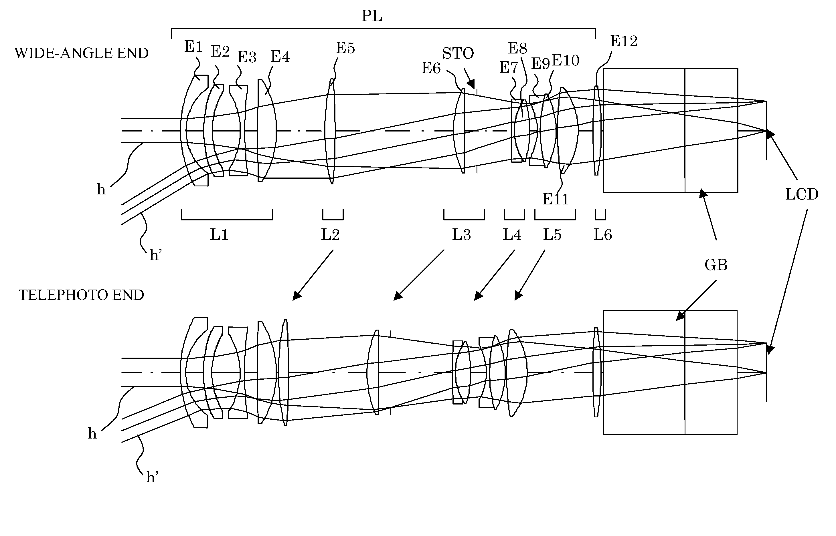
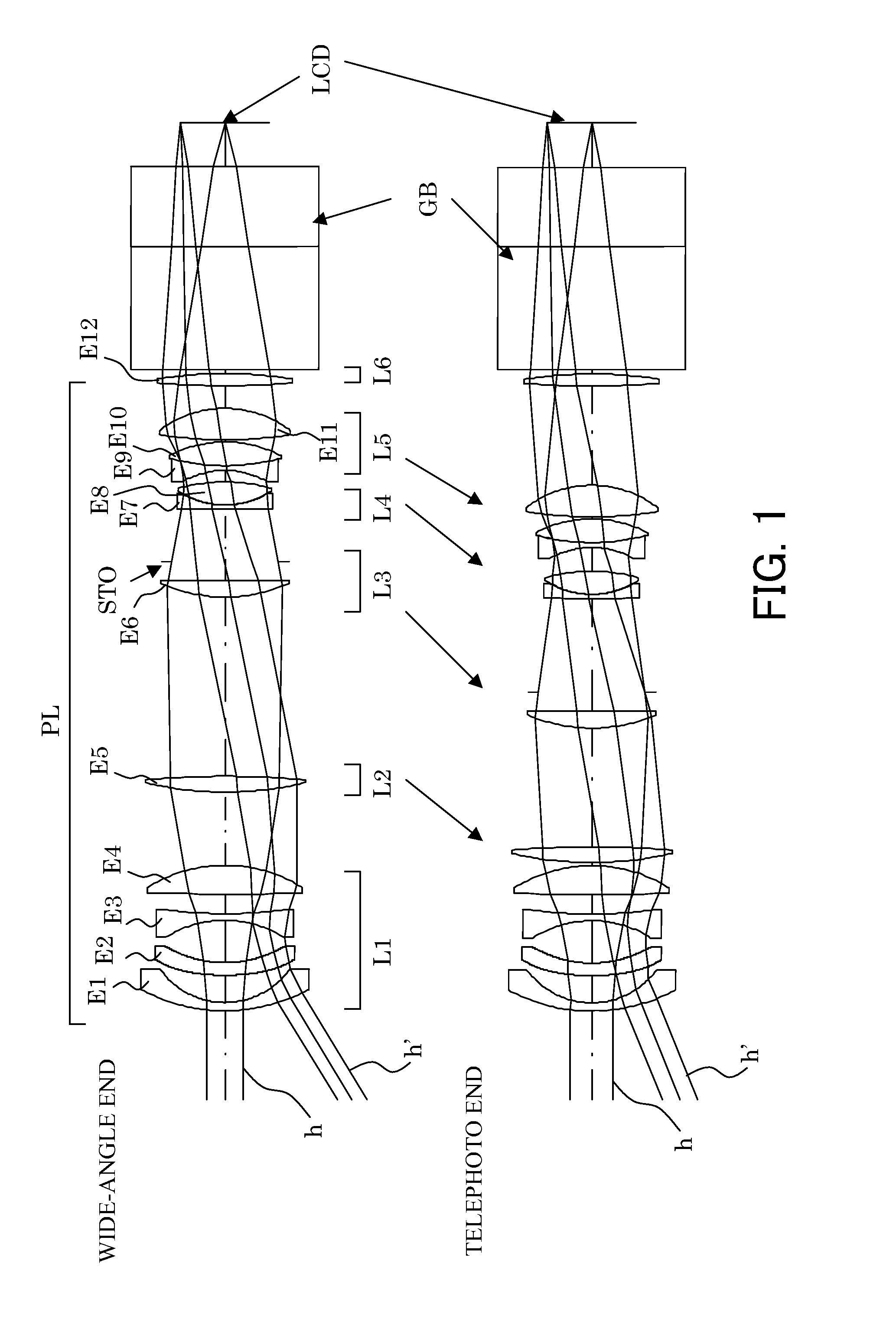
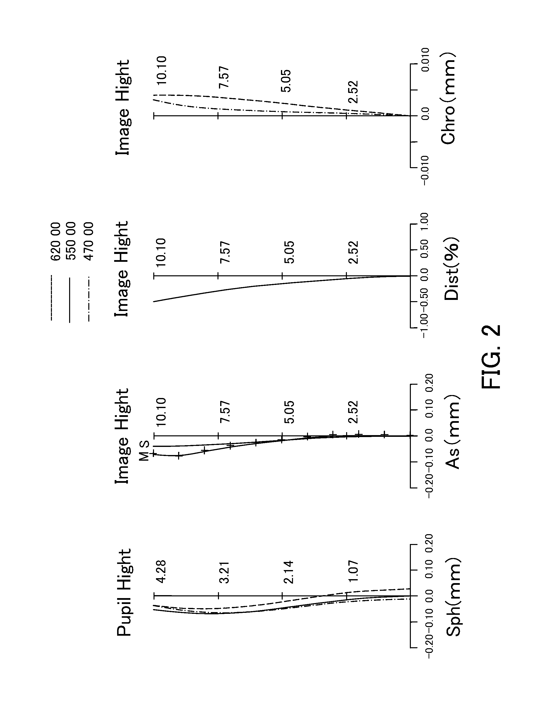
[0117]FIG. 1 schematically shows the image projection optical system of Embodiment 1. FIGS. 2 and 3 show spherical aberration (Sph), astigmatism (As), distortion (Dst), and chromatic aberration of magnification (Chro) at the wide-angle end and at the telephoto end, respectively, when numerical values of Numerical Example 1 corresponding to this embodiment are shown in millimeters.

[0118]FIG. 1 shows the image projection optical system including a six-lens-unit zoom lens having a power arrangement of negative, positive, positive, negative, positive, and positive in order from the magnification side.

[0119]The first lens unit L1 is constituted by, in order from the magnification side, a negative meniscus lens element E1 having a magnification-side convex surface, an aspheric lens element E2, a negative lens element E3 having a strong power, and a positive lens element E4 having a reduction-side convex surface with a strong power.

[0120]The negative meniscus lens element E1 has a negative...

embodiment 2

[0134]FIG. 4 schematically shows the image projection optical system of Embodiment 2. FIGS. 5 and 6 show spherical aberration (Sph), astigmatism (As), distortion (Dst), and chromatic aberration of magnification (Chro) at the wide-angle end and at the telephoto end, respectively, when numerical values of Numerical Example 2 corresponding to this embodiment are shown in millimeters.

[0135]FIG. 4 shows the image projection optical system including a six-lens-unit zoom lens having a power arrangement of negative, positive, positive, positive, negative, and positive in order from the magnification side.

[0136]The zoom lens of this embodiment is different from that of Embodiment 1 in that the synthesized power of a fourth lens unit L4 is positive and that of a fifth lens unit L5 is negative. Lens units L1 to L6 in this embodiment respectively have similar functions to those of the lens units L1 to L6 in Embodiment 1.

[0137]The zoom lens of this embodiment can also achieve good optical perfor...

embodiment 3

[0138]FIG. 7 schematically shows the image projection optical system of Embodiment 3. FIGS. 8 and 9 show spherical aberration (Sph), astigmatism (As), distortion (Dst), and chromatic aberration of magnification (Chro) at the wide-angle end and at the telephoto end, respectively, when numerical values of Numerical Example 3 corresponding to this embodiment are shown in millimeters.

[0139]FIG. 7 shows the image projection optical system including a six-lens-unit zoom lens having a power arrangement of negative, positive, positive, positive, positive, and positive in order from the magnification side.

[0140]The zoom lens of this embodiment is different from that of Embodiment 1 in that two lens units corresponding to the fourth and fifth lens units L4 and L5 in Embodiment 1 constitute a fifth lens unit L5. Of the four lens elements E1 to E4 constituting the first lens unit L1 in Embodiment 1, three magnification-side lens elements E1 to E3 serve as a first lens unit in this embodiment an...


PUM


Abstract

An image projection optical system introduces light from an image-forming element by a zoom lens via an optical element. The optical element satisfies Σ(Di×Ndi) / fw>4.0. The zoom lens includes, in order from a magnification side, first and second lens units, and lens units disposed closer to a reduction side than the second lens unit. The first lens unit is a negative lens unit. The lens units disposed closer to the reduction side than the second lens unit satisfy |dn / dt|<1.0×10⁻⁵. Magnification-side positive lens elements disposed closer to the magnification side than a negative lens element whose effective diameter is smallest in the lens units disposed closer to the reduction side than the second lens unit satisfy {9.0×Σ(1 / fpA)+5.0×Σ(1 / fpB)+0.5×Σ(1 / fpC)} / Σ(1 / fp)<1. Reduction-side positive lens elements disposed closer to the reduction side than the negative lens element whose effective diameter is smallest satisfy {9.0×Σ(1 / fpA)+0.3×Σ(1 / fpB)+2.0×Σ(1 / fpC)} / Σ(1 / fp)<1. Chromatic aberration is corrected and focus variations by temperature changes are reduced.

Description

BACKGROUND OF THE INVENTION[0001]The present invention relates to an image projection apparatus, such as a projector, an image projection optical system including a projection lens that is a zoom lens, which is used for the image projection apparatus.[0002]Image projection apparatuses (projectors) projecting light from an image-forming element such as a liquid crystal panel onto a projection surface such as a screen should satisfy the following requirements.[0003]1. In a three-panel projector using three image-forming elements for R, G, and B, a space is required where optical elements, such as a color-combining prism combining three color light components from the three image-forming elements and a polarizing element, between the image-forming elements and a projection lens. Thus, a back focus of the projection lens needs to be long to some extent.[0004]2. The projection lens needs to be a telecentric optical system whose image-forming-element side pupil is located at infinite dist...

Claims


Application Information

Patent Timeline
Patent Type & Authority Patents(United States)
IPC IPC(8): G02B15/14
CPCG02B13/16G02B15/177G02B15/145531G02B15/1465
Inventor SUGITA, SHIGENOBU
Owner CANON KK
Why Eureka
Try Eureka