Optical lens having antireflective structure

an optical lens and anti-reflective coating technology, applied in the field of optical lenses having anti-reflective coatings, can solve the problems of small thickness of anti-reflective coating applied to the peripheral area of the lens compared with that around the optical axis, difficult to reduce the beam spot diameter, and difficult to provide a high-na optical lens to which an appropriate coating is applied

Active Publication Date: 2009-06-09
PANASONIC CORP
View PDF5 Cites 25 Cited by
  • Summary
  • Abstract
  • Description
  • Claims
  • Application Information

AI Technical Summary

Benefits of technology

[0015]According to the present invention, an optical lens in which the light reflection at the interface can be suppressed can be provided.

Problems solved by technology

However, according to the method of applying an antireflective coating, since the curvature in the peripheral area of the high-NA lenses is high, the thickness of the antireflective coating applied to the peripheral area of the lens is small compared with that around the optical axis.
For this reason, the laser beam transmittance in the lens peripheral area is low and it is therefore difficult to reduce the beam spot diameter.
For this reason, it is difficult to provide a high-NA optical lens to which an appropriate coating is actually applied according to the design condition.
In addition, the applied antireflective coating has a large thickness error from the design thickness, so that it is extremely difficult to obtain an optical lens having excellent transmittance.
However, the thickness error from the design thickness increases as the curvature of the lens surface increases.
For this reason, in the high-NA optical lenses, the thickness error in the lens peripheral area is large, so that it is difficult for the light quantity distribution to be uniform.
Consequently, the overall transmittance of the optical lens is low, so that it is difficult to form an excellent beam spot on the optical disk.
As described above, it is difficult to provide a high-NA optical lens provided with excellent transmittance by the application of an antireflective coating.

Method used


Image

  • Optical lens having antireflective structure
  • Optical lens having antireflective structure
  • Optical lens having antireflective structure

Examples


first embodiment

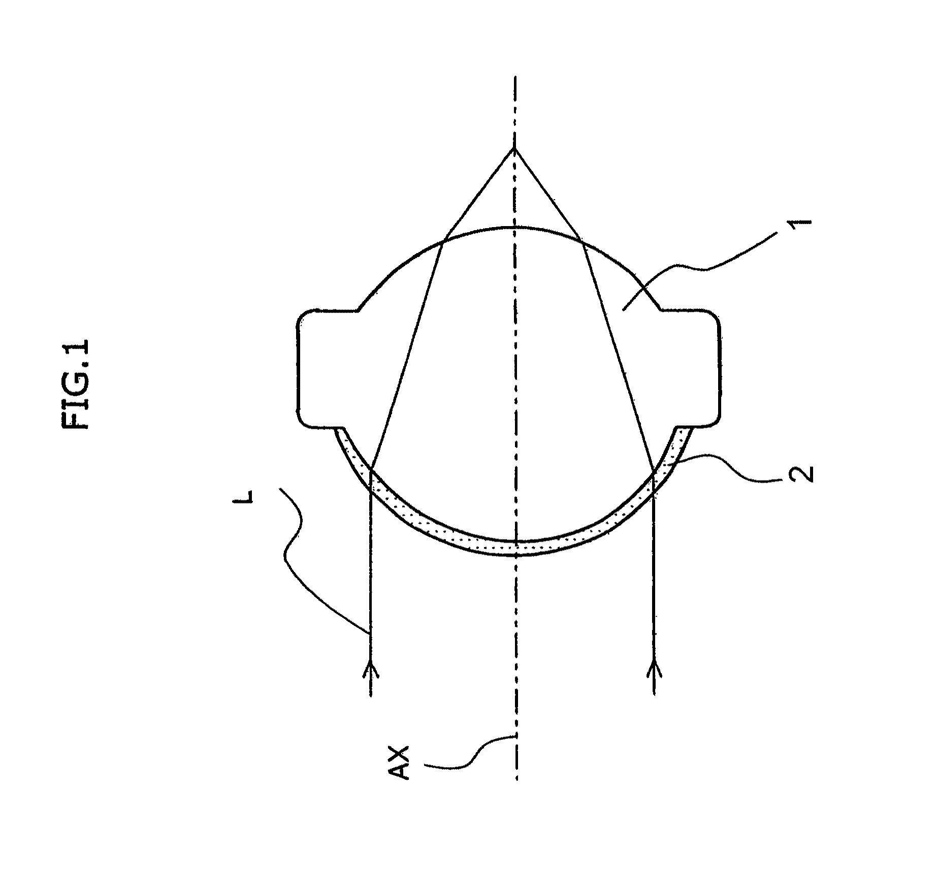
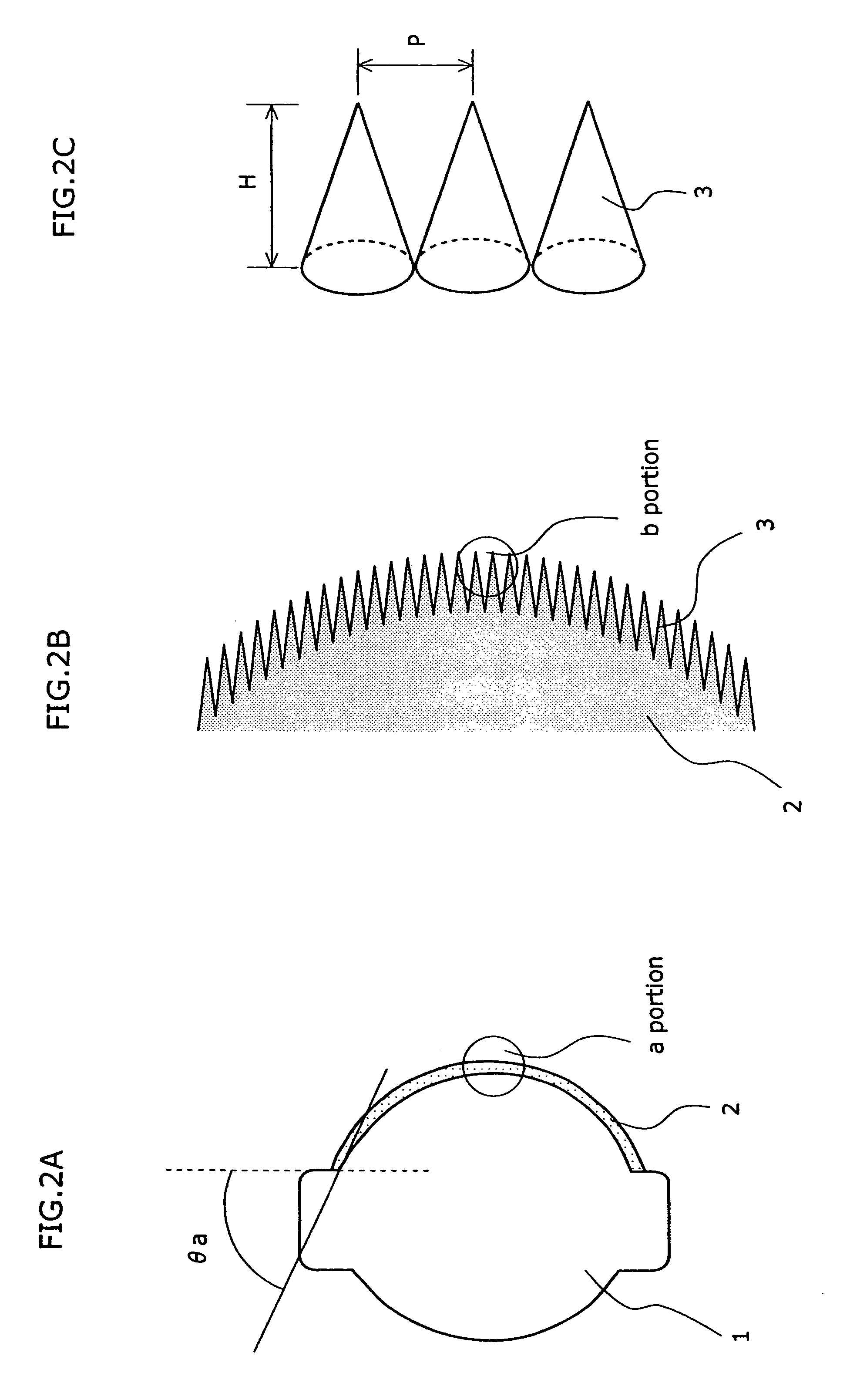
[0028]FIGS. 1 and 2A to 2C are views of an optical lens according to a first embodiment of the present invention. FIG. 1 is a light beam view of the optical lens 1. FIG. 2A is a schematic structural view. FIG. 2B is a schematic enlarged view of an a portion. FIG. 2C is a schematic enlarged view of a b portion. In the present embodiment, the wavelength of the laser beam used is near 400 nanometers, and the optical lens 1 has an NA of 0.85.

[0029]In FIG. 1, a laser beam L emitted from a non-illustrated laser source is incident on the optical lens 1. An antireflective structure 2 that prevents the reflection of the incident light is formed on the lens surface where the light beam L is incident. The light beam L passes through the antireflective coating 2 and the optical lens 1, and then, condenses in a predetermined position.

[0030]Macroscopically, the optical lens 1 is a convex lens the surfaces of which are curved. To realize a high NA, the optical lens 1 has a configuration that incre...

second embodiment

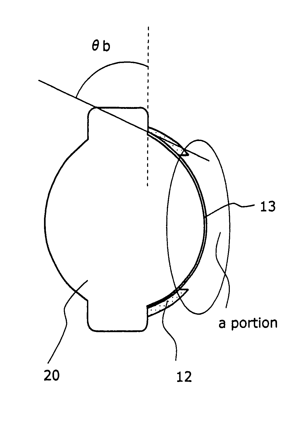
[0043]FIGS.4A to 4C are views showing an optical lens according to a second embodiment. FIG. 4A is a schematic cross-sectional view. FIG. 4B is an enlarged view of the a portion. FIG. 4C is an enlarged view of the b portion. While the optical lens 20 according to the present embodiment has a substantially similar structure to the optical lens according to the first embodiment, it is different in the following points: The antireflective structure is formed as a sheet 12 independent of the optical lens 20, and the sheet 12 is pasted to a lens peripheral area where the curvature of the lens surface is high. Here, the lens peripheral area is an area where when the height of incidence of the lens surface is h and the maximum effective diameter of the lens is hmax, h / hmax is not less than 0.6. Particularly, it is desirable that the antireflective structure be provided in an area where h / hmax is not less than 0.7 where the reduction in light quantity is large.

[0044]The optical lens 20 has ...


PUM

PropertyMeasurementUnit
inclination angleaaaaaaaaaa
wavelengthaaaaaaaaaa

Abstract

An optical lens in which reflection is suppressed is provided by providing the optical lens with: a convex lens surface having, when the angle between a plane in contact with the lens surface and a direction perpendicular to the optical axis is an inclination angle, a maximum inclination angle of not less than 35 degrees and less than 90 degrees; and an antireflective structure provided on the lens surface and including structural elements that have a predetermined shape and are periodically arranged in an array form with a pitch smaller than the shortest wavelength of the incident light.

Description

BACKGROUND OF THE INVENTION[0001]1. Field of the Invention[0002]The present invention relates to an optical lens having an antireflective structure, and more specifically, to an optical lens having an antireflective structure on a lens surface.[0003]2. Description of the Background Art[0004]Transmissive optical elements are used for various optical systems such as those for cameras, projectors, and optical pickup devices. To obtain a predetermined optical performance, these optical systems require optical elements that efficiently transmit light. On the other hand, a technology is known of applying an antireflective coating along the surface of optical elements.[0005]Research has been pursued on high-density and large-capacity optical disks such as DVDs (digital versatile disks) and Blue-ray disks(R). To play back information recorded on an optical disk, a laser beam is condensed on the optical disk by an objective lens, and the reflected light caused by the condensation is applied ...

Claims


Application Information

Patent Timeline
Patent Type & Authority Patents(United States)
IPC IPC(8): G02B3/02
CPCG02B1/11G02B5/045
Inventor HAYASHI, KATSUHIKOTANAKA, YASUHIROYAMAGATA, MICHIHIRO
Owner PANASONIC CORP
Why Eureka
Try Eureka