Control circuit for current and voltage control in a switching power supply

a control circuit and power supply technology, applied in the direction of dc-dc conversion, power conversion systems, instruments, etc., can solve the problems of direct ohmic connection between the electricity network system and the electrical device, noise produced by the frequency-controlled control of the switching power supply, power supply audible noises that may be generated, etc., to reduce the load dependency of output voltage, less noise, and less waviness of output voltage

Active Publication Date: 2009-06-09
MYPAQ HLDG LTD
View PDF7 Cites 15 Cited by
  • Summary
  • Abstract
  • Description
  • Claims
  • Application Information

AI Technical Summary

Benefits of technology

[0038]An improved switch mode power supply may be provided, that is able to reduce the load dependency of the output voltage and generates less noise and features a less waviness of the output voltage. The improved switch mode power supply further is less susceptable to failure in the determination in time of the switch-on point in time
[0039]In one embodiment a control circuit for controlling the output voltage and / or the output current in a switching power supply controlled by the primary-sided is provided, wherein the switching power supply comprises a transformer having a primary-sided and secondary-sided main winding. Electrical energy pulses are transmitted from the primary-sided to the secondary-sided main winding. A primary-sided switch is provided for switching on and off the primary current through the primary-sided main winding in response to a control signal of the control circuit. A primary-sided auxiliary winding is provided, in which after switching off the primary-sided switch a voltage pulse is induced, wherein the level of the voltage pulse depends on the load at the secondary side. Furthermore, a sample and holding device is provided for sampling and storing a level of the voltage pulse for generating a control variable, wherein the control signal is generated on the basis of the control variable. In addition, a primary current comparator determines a switch-off point in time of the primary-sided switch depending on the primary current. The control variable is fed back to the primary current comparator in a manner that the switch-off point in time of the primary-sided switch can additionally be influenced depending on the control variable in a manner that the time during which the primary current flows through the primary-sided main winding is reduced differently.

Problems solved by technology

Furthermore, a direct ohmic connection between the electricity network system and the electrical device is not allowed for safety reasons.
A disadvantage of switching power supplies are the audible noises that may be generated.
On the other hand, noise is produced by the frequency-controlled control of the switching power supply.
As already mentioned, the problem exists in the known control circuit, that the output voltage depends on the load, since the frequency is adjusted depending on the deviation of the auxiliary voltage from the target value.
A further problem of the cited control circuit is that in the case of a low load energy-rich pulses with low frequencies are switched, wherein audible noise can be produced.
A problem connected therewith is also the relatively large waviness of the output voltage.
A further problem is the susceptance to failure of the clock frequency control.
For a comparatively long period of time before the intersecting point of the exponential reference voltage with the output voltage kept constant, the difference between the reference and the output voltage is therefore small, which may lead to significant interferences of the determination of the time.

Method used


Image

  • Control circuit for current and voltage control in a switching power supply
  • Control circuit for current and voltage control in a switching power supply
  • Control circuit for current and voltage control in a switching power supply

Examples


Embodiment Construction

[0052]The illustrative embodiments of the present invention will be described with reference to the figure drawings like elements and structures indicated by like reference numbers.

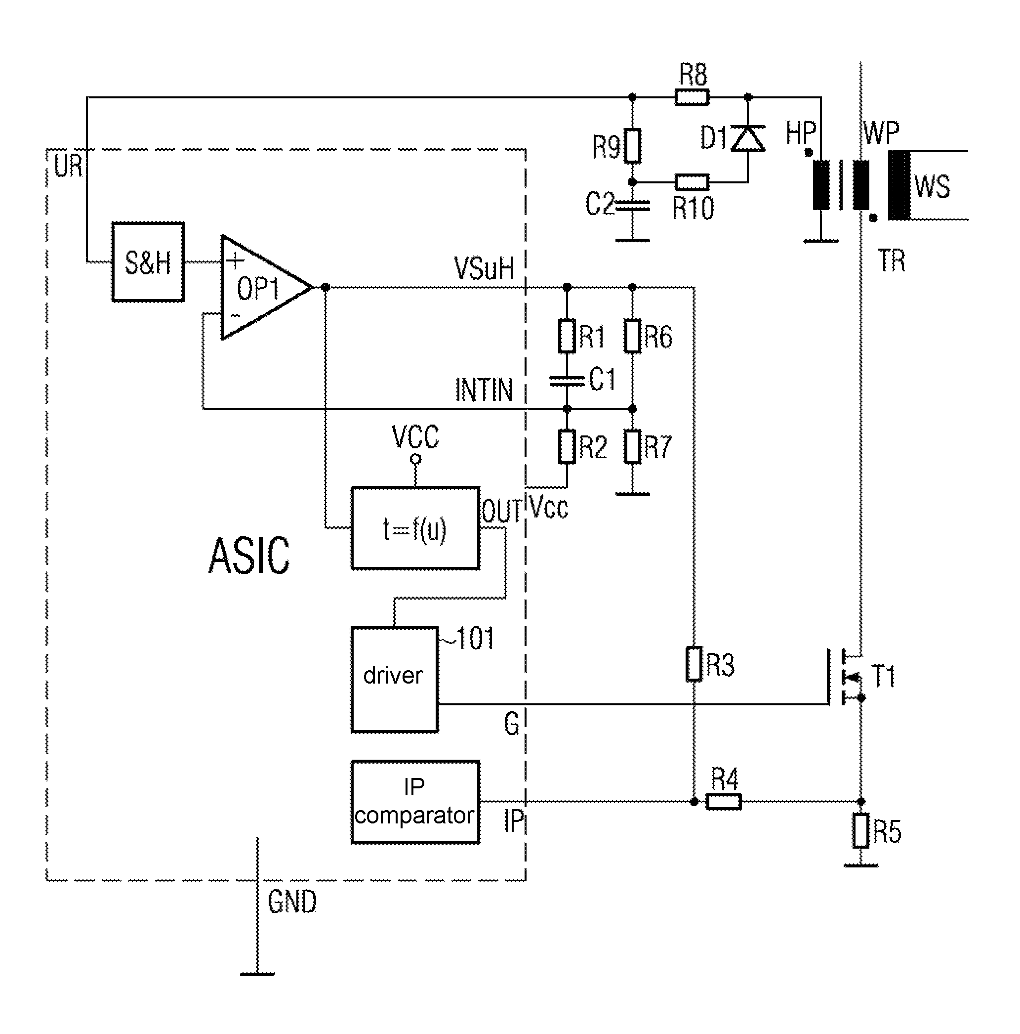
[0053]FIG. 1 shows a block diagram of a control circuit for controlling the output voltage and / or the output current in a switching power supply controlled by the primary side according to a first embodiment.

[0054]As explained above, the switch-off point in time of the transistor T1 in the control circuit according to reference WO 2004 / 082119 A2 is determined without influence from the control variable. The transmitted energy per pulse is therefore not dependent from the output voltage. To provide the required voltage at the output, the control can only set the clock frequency. If more energy is required, when a large load applies at the output, the frequency is increased. Accordingly, in the case of low load, the frequency is lowered again. In the case of low load, the same energy per pulse is transmitte...


PUM


Abstract

A control circuit and method for controlling the output voltage and / or the output current of a switching power supply. The control circuit includes a transformer with a primary-side and a secondary-side main winding and a primary-side switch for switching on and off the primary current through the primary-side main winding in response to a control signal of the control circuit. The control circuit also includes a primary-side auxiliary winding operable to induce a voltage pulse after the primary-side switch is turned off, and a sample and hold device for sampling and storing a level of the voltage pulse for generating a control variable.

Description

BACKGROUND OF THE INVENTION[0001]1. Field of the invention[0002]The present invention refers to a circuit for current and voltage control in a switching power supply controlled by the primary side. The switching power supply comprises a transformer with a primary-sided and secondary-sided main winding, wherein electrical energy pulses are transmitted from the primary side to the secondary side. A primary-side switch switches on and off a primary current through the primary-sided main winding. Furthermore, the invention refers to a method of controlling the output voltage and the output current in a switching power supply controlled on the primary side.[0003]2. Description of the Related Art[0004]The operation of electrical devices usually requires a precisely defined supply voltage so that these devices operate properly, wherein this supply voltage is in many cases independent of the mains voltage provided by the electricity network. Consequently, many electric devices, such as comp...

Claims


Application Information

Patent Timeline
Patent Type & Authority Patents(United States)
IPC IPC(8): H02M3/335
CPCH02M3/33523H02M3/158H02M3/335
Inventor BERGHEGGER, RALF SCHRODER GENANNT
Owner MYPAQ HLDG LTD
Why Eureka
Try Eureka