System of stacked concrete blocks, each block having a tire wall stack therewithin surrounding a hollow core through which a vertical reinforcing member extends and reinforcing bars in mortar in void between adjacent blocks

a technology of concrete blocks and stacked blocks, applied in the direction of walls, buildings, instruments, etc., can solve the problems of low tire usage, inefficient stackability, and risk of slippage and movement, and achieve the effect of avoiding slippag

Inactive Publication Date: 2009-06-16
SHAW REECE F
View PDF45 Cites 37 Cited by
  • Summary
  • Abstract
  • Description
  • Claims
  • Application Information

AI Technical Summary

Benefits of technology

[0009]In another embodiment, the void—otherwise occupied by the tire stack—is formed in the mold and left hollow, thus lightening the total weight of the block. Outwardly, the “void” block resembles the tire stack block with the exception of the undersurface which reveals a formed annulus—which creates the hollow annular structural core—and the void space around it which extends to the perimeter walls. Alternatively, the tire bundle stack can be placed in the form in the non-compressed state, creating a lighter void space than would otherwise be occupied by a compressed tire bundle stack.
[0022](8) As a system, avoiding slippage relative to itself and to the underlying foundation.

Problems solved by technology

Prior concrete structures incorporating used tires have usually suffered from one or more of the following problems or disadvantages: (1) low tire usage, (2) bare tires exposed to water in the environment, (3) risk of slippage and movement during use on inclined dirt banks, (4) inefficient stackability, (5) requiring field welding to connect units, and (6) insufficient system structural performance capability.
Each of these systems suffers from one or more of the previously described problems or disadvantages.
Consequently, they either make relatively low or no use of used tires, allow bare tires to be exposed to water, run the risk of slippage and movement during use on inclined dirt banks, offer inefficient stackability, require field welding to provide structural continuity, and / or have insufficient system structural performance capability.

Method used


Image

  • System of stacked concrete blocks, each block having a tire wall stack therewithin surrounding a hollow core through which a vertical reinforcing member extends and reinforcing bars in mortar in void between adjacent blocks
  • System of stacked concrete blocks, each block having a tire wall stack therewithin surrounding a hollow core through which a vertical reinforcing member extends and reinforcing bars in mortar in void between adjacent blocks
  • System of stacked concrete blocks, each block having a tire wall stack therewithin surrounding a hollow core through which a vertical reinforcing member extends and reinforcing bars in mortar in void between adjacent blocks

Examples


Embodiment Construction

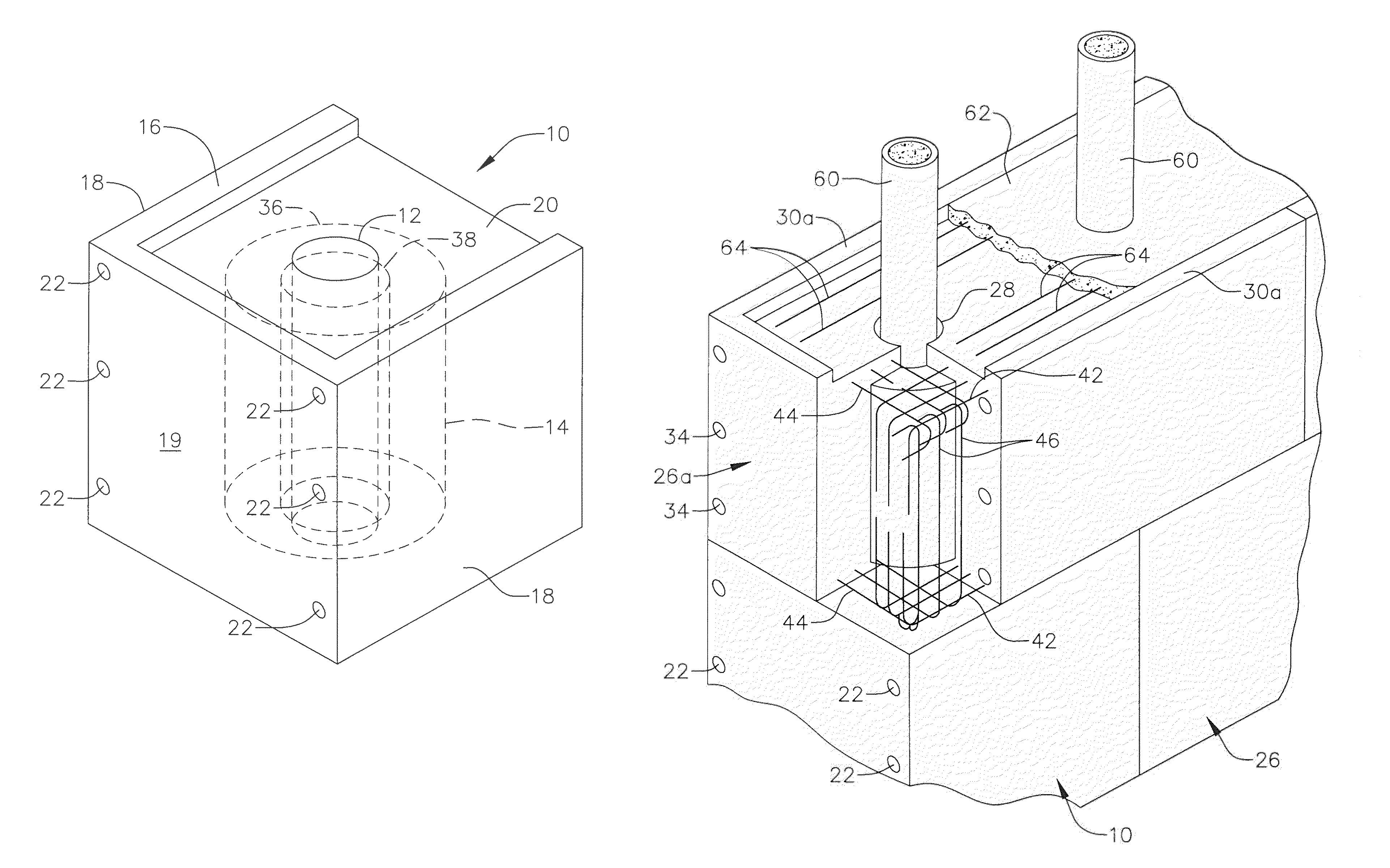
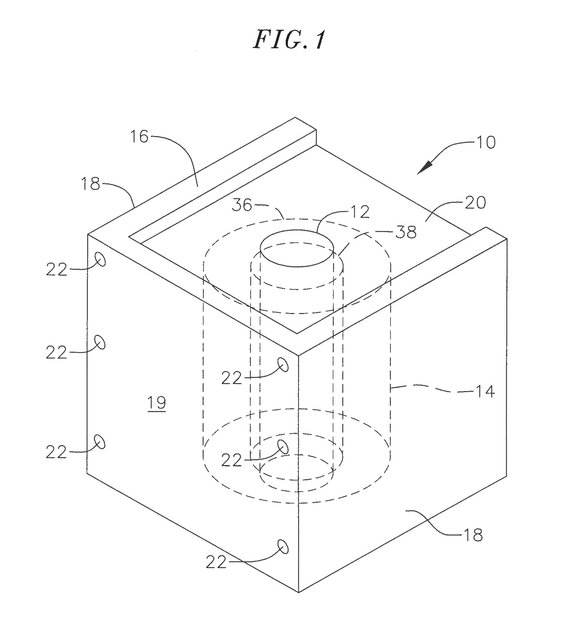
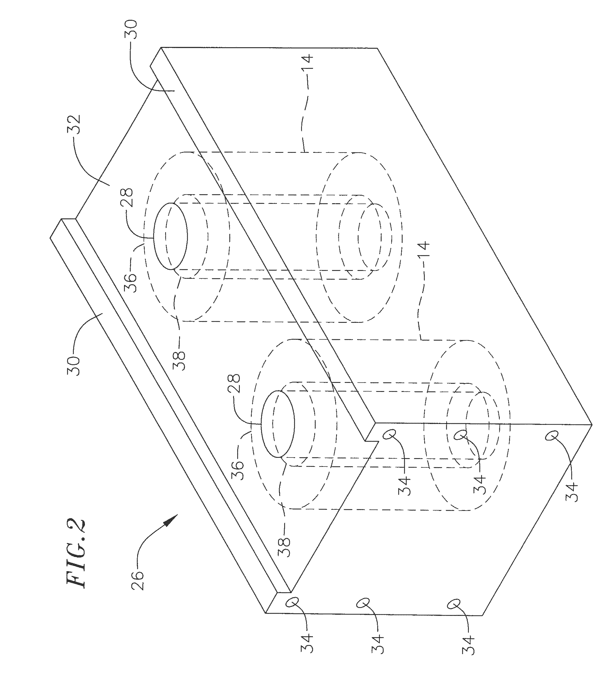
[0045]The drawings illustrate structural systems utilizing oversized hollow unit precast concrete blocks and a method for making and using them. Referring to one embodiment of the invention in FIG. 1, a precast concrete building block 10 comprises a compressed annular tire wall stack unit 14 encased in reinforced concrete. In cross-section, the block is square if a single tire stack is used and rectangular if two or more stacks are used. The block has a hollow core 12 extending through the stack unit to provide for vertical reinforcement. FIG. 1 illustrates the block 10 shaped generally as a cube, having a single tire stack unit 14 disposed centrally within the block. The precast block 10 includes a three-sided upwardly projecting lip 16 of generally uniform height spanning two opposite sides 18 and an end 19 of the block. This forms a shallow recess 20 of generally rectangular shape on an upper surface of the block within the outer lip. The recess 20 provides for bond beam (horizon...


PUM


Abstract

An article of manufacture for building concrete structures from precast blocks and the process for making the structural system. The block comprises one or more annular tire wall stack units embedded in reinforced concrete. Prestressing and / or post-tensioning structural reinforcing techniques are used with assembled building blocks. The blocks are made by placing used tire stacks in a form that centralizes the stacks so that reinforced concrete can be placed around them while maintaining a hollow core through the stacks. Horizontal interlocking between blocks uses reinforcing bars and / or a tongue and groove configuration, and / or post-tension wire strand placed in a recess or post-tension tubes formed in the blocks and mortared in-place during construction. Vertical interlocking between blocks uses a tongue-and-groove interlock, shiplap splicing, and reinforcing bars. Post-tension wire strand, pipe, or H-piles are placed in and through the stacks and mortared in-place during construction.

Description

CROSS-REFERENCE TO RELATED APPLICATIONS[0001]This application claims the benefit of provisional patent application No. 60 / 561,702 filed Apr. 13, 2004, the entire disclosure of which is incorporated herein by this reference.FIELD OF THE INVENTION[0002]This invention relates to precast concrete building structures, and more specifically, to structures which may include compressed vehicular tires as a component.BACKGROUND OF THE INVENTION[0003]Various concrete structures have been disclosed for use in land and marine based applications. These applications include civil and structural applications such as walls, retaining walls, and breakwaters. These structures have included used tires as a component. Prior concrete structures incorporating used tires have usually suffered from one or more of the following problems or disadvantages: (1) low tire usage, (2) bare tires exposed to water in the environment, (3) risk of slippage and movement during use on inclined dirt banks, (4) inefficien...

Claims


Application Information

Patent Timeline
Patent Type & Authority Patents(United States)
IPC IPC(8): E04B2/18E04B2/20E04C1/41E04B2/02E04B2/04E04B2/16E04B2/22E04C2/04
CPCE04B2/04E04B2/16E04B2/18E04B2/22G06K7/1417G06K7/1443G06K7/1456E04B2002/0208E04B2002/0219E04B2002/0284
Inventor SHAW, REECE F.
Owner SHAW REECE F
Why Eureka
Try Eureka