Touch sensor operated vehicle room lamp to be turned on and off

a technology of vehicle room lamps and touch sensors, which is applied in the direction of fixed installation, transportation and packaging, lighting and heating equipment, etc., can solve the problems of reducing the overall brightness of illumination, shortened service life of the system, and small illumination area, so as to improve the level of brightness through the lens, prevent failure, and simple structure

Active Publication Date: 2009-06-16
T & T
View PDF14 Cites 32 Cited by
  • Summary
  • Abstract
  • Description
  • Claims
  • Application Information

AI Technical Summary

Benefits of technology

[0007]The present invention has been made in view of the problems described above. An object of the present invention is to provide a vehicle interior light system that has a small touch sensor on the back surface of a lens such that a lamp can be turned on and off when the lens is touched or approached by a finger or the like, achieves a high level of brightness by substantially uniformly illuminating the entire surface of the lens with the lamp in a state where there is virtually no interference, eliminates the need for some mechanical structures, requires no mechanical switch, and thus has a long service life.
[0012]In the above-described vehicle interior light system of the present invention, since the lamp can be turned on and off by bringing a finger or the like close to the touch sensor on the back surface of the lens, some known mechanical parts and a mechanical switch become no longer needed. This not only allows the prevention of failures caused by mechanical wear, but also increases the level of brightness through the lens, as the transmission of light from the lamp is obstructed only by the small touch sensor.
[0013]Moreover, since the touch sensor is affixed to the back surface of the lens, or is vertically arranged on the substrate and positioned on the back surface of the lens, it is possible to provide a vehicle interior light system that is simple in structure, free from failures, and inexpensive.
[0014]Moreover, when the vehicle interior light system is configured such that the touch sensor is illuminated from behind, the position of the touch sensor can be easily identified even in the dark, such as at night, and the lamp can be easily and reliably turned on. When a marker for indicating the position of the touch sensor is formed on the surface of the lens, the position of the touch sensor can be identified at a glance under bright conditions, such as in the daytime.
[0015]Moreover, using a light-emitting diode (such as a white light-emitting diode) as the lamp not only allows power savings, but also ensures safe turning-off operation since the lens is not heated by the light-emitting diode, which generates only a small amount of heat. Moreover, the lens covering the entire opening of the enclosure not only allows the lamp to illuminate a large area and to produce a high level of brightness, but also provides a good appearance.

Problems solved by technology

This is disadvantageous in that the illuminated area is small.
In the interior light system for vehicles described above, it is possible that the internal push-button switch interferes with the transmission of light near the light source, blocks the light from uniformly illuminating the entire surface of the lens, and thus lowers the overall brightness of illumination.
Moreover, since the interior light system has a mechanism that allows the lens to rotate, the service life of the system may be shortened due to wear resulting from the rotation of the lens.

Method used


Image

  • Touch sensor operated vehicle room lamp to be turned on and off
  • Touch sensor operated vehicle room lamp to be turned on and off
  • Touch sensor operated vehicle room lamp to be turned on and off

Examples


first embodiment

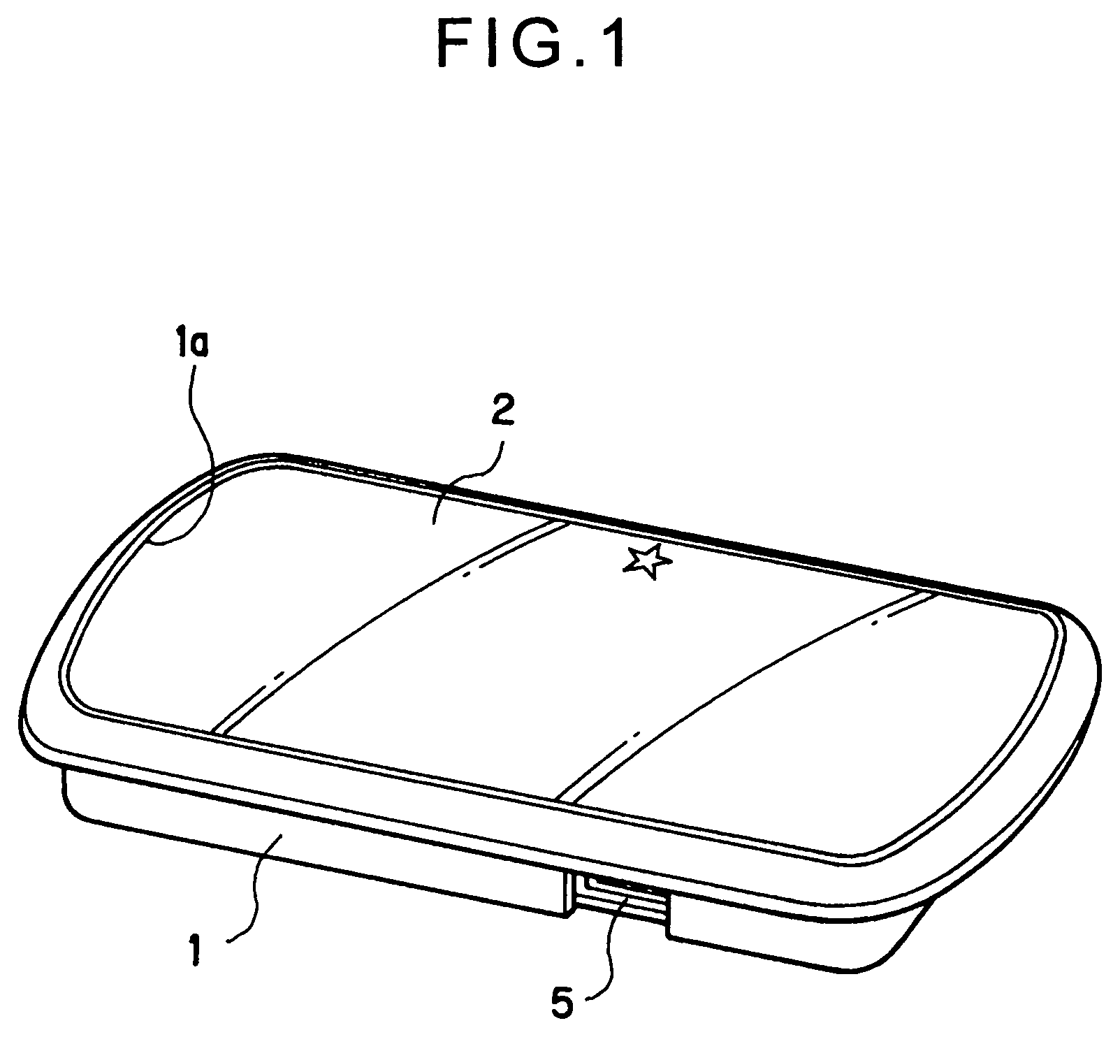
[0021]A vehicle interior light system according to the first embodiment of the present invention will now be described with reference to FIG. 1 and FIG. 2.

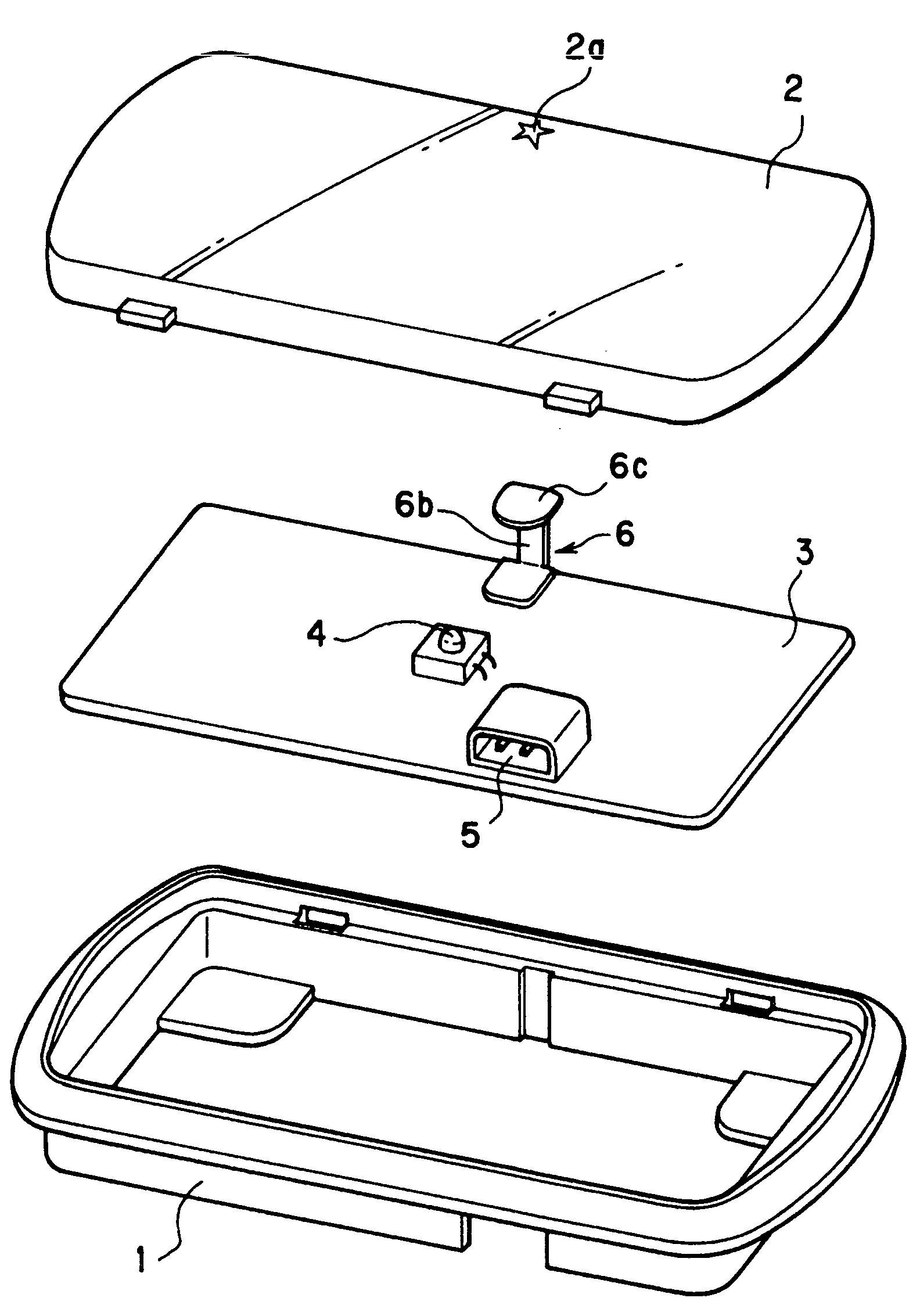
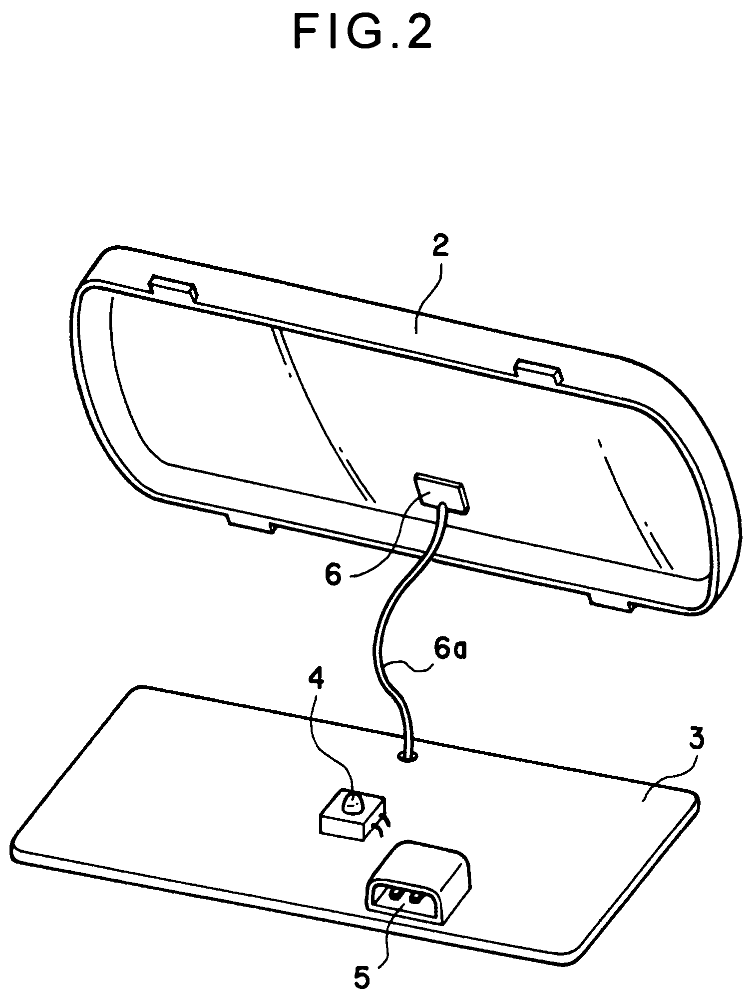
[0022]A lens 2 is disposed over an opening 1a of an enclosure 1 to cover substantially the entire surface of the enclosure 1. A substrate 3 (shown in FIG. 2) is secured internally to the enclosure 1. A lamp 4, such as a white light-emitting diode, and a connector 5 for connection to a power source are soldered to the substrate 3. A touch sensor 6 made of a conductive member or a semiconductive member, such as a metal plate or an aluminum foil, is affixed to the back surface of the lens 2 and is connected via a lead 6a to a control circuit (not shown) mounted on the substrate 3. The control circuit includes a sensor circuit and a switching circuit. The sensor circuit detects a change in capacitance when a human body touches or approaches the lens 2 provided with the touch sensor 6 on the back surface thereof. The switching circuit ...

second embodiment

[0024]The second embodiment will now be described with reference to FIG. 3. The same reference numerals as those in the first embodiment denote the same or corresponding members and the descriptions thereof will be omitted here.

[0025]In the second embodiment, the touch sensor 6 connected to the control circuit is made of a conductive member, such as a metal plate, and is soldered to the substrate 3 at one end. A support post 6b of the touch sensor 6 extends vertically from the substrate 3 and is attached to a contact part 6c at the other end of the touch sensor 6. The contact part 6c is in close contact with the back surface of the lens 2 or is arranged near the back surface of the lens 2.

[0026]In the vehicle interior light system of the second embodiment configured as described above, the contact part 6c of the touch sensor 6 is in contact with or close to the back surface of the lens 2. Therefore, when a human finger touches or approaches the marker 2a of the lens 2, the control c...

third embodiment

[0027]The third embodiment will now be described with reference to FIG. 4. The same reference numerals as those in the second embodiment denote the same or corresponding members and the descriptions thereof will be omitted here.

[0028]In the third embodiment, the contact part 6c of the touch sensor 6 is provided with a hole 6d for use in illumination, while an auxiliary lamp (light-emitting diode) 7 for indicating the position of the touch sensor 6 is disposed immediately below the hole 6d and soldered to the substrate 3.

[0029]The vehicle interior light system of the third embodiment described above is configured such that the auxiliary lamp 7 is ON while headlights are ON for night driving or the like. Therefore, light emitted from the auxiliary lamp 7 is projected onto the surface of the lens 2 through the hole 6d when it is dark inside the vehicle, for example, at night. This allows the position of the touch sensor 6 to be immediately identified and thus the lamp 4 to be reliably ...


PUM


Abstract

A vehicle interior light system includes a lamp, an enclosure internally provided with the lamp, a lens attached to the front of the enclosure, a touch sensor arranged on the back surface of the lens, and a control circuit including a sensor circuit and a switching circuit. The sensor circuit is configured to detect the capacitance of a human body when the lens is touched or approached by a finger or the like. The switching circuit is configured to turn the lamp on and off in response to an output from the sensor circuit.

Description

BACKGROUND OF THE INVENTION[0001]1. Field of the Invention[0002]The present invention relates to a vehicle interior light system to be mounted on the interior roof of a vehicle, and particularly to a vehicle interior light system capable of turning an interior lamp on and off when the tip of a finger or the like approaches a touch sensor provided on a lens.[0003]2. Description of the Related Art[0004]Typical known vehicle interior light systems have a slide switch or a push-button switch on an enclosure so that a lamp inside the light system can be turned on and off by sliding the slide switch or pressing the push-button switch. Since such a vehicle interior light system has a switch on the enclosure, the size of a lens used in the light system is small relative to the size of the enclosure. This is disadvantageous in that the illuminated area is small.[0005]To solve such a problem, the present applicant developed an interior light system for vehicles as disclosed in Japanese Unexam...

Claims


Application Information

Patent Timeline
Patent Type & Authority Patents(United States)
IPC IPC(8): F21V29/00
CPCB60Q3/0293B60Q3/0296B60Q3/82B60Q3/80
Inventor KUWANA, ISAMUOKANO, HIROFUMI
Owner T & T
Why Eureka
Try Eureka