
Film type antenna and mobile communication terminal case using the same

a mobile communication terminal and film-type technology, applied in the direction of resonant antennas, disturbance protection, protective materials radiating elements, etc., can solve the problems of affecting the miniaturization and portability of the terminal, the antenna type is more likely to be destructed, and the miniaturization can also be a problem

Inactive Publication Date: 2009-06-16
SAMSUNG ELECTRO MECHANICS CO LTD
View PDF12 Cites 11 Cited by
  • Summary
  • Abstract
  • Description
  • Claims
  • Application Information

AI Technical Summary

Benefits of technology

The film type antenna reduces mounting space requirements, enhances electric conductivity, and conceals the radiator pattern, improving the miniaturization and durability of mobile communication terminals while maintaining radiation characteristics.

Problems solved by technology

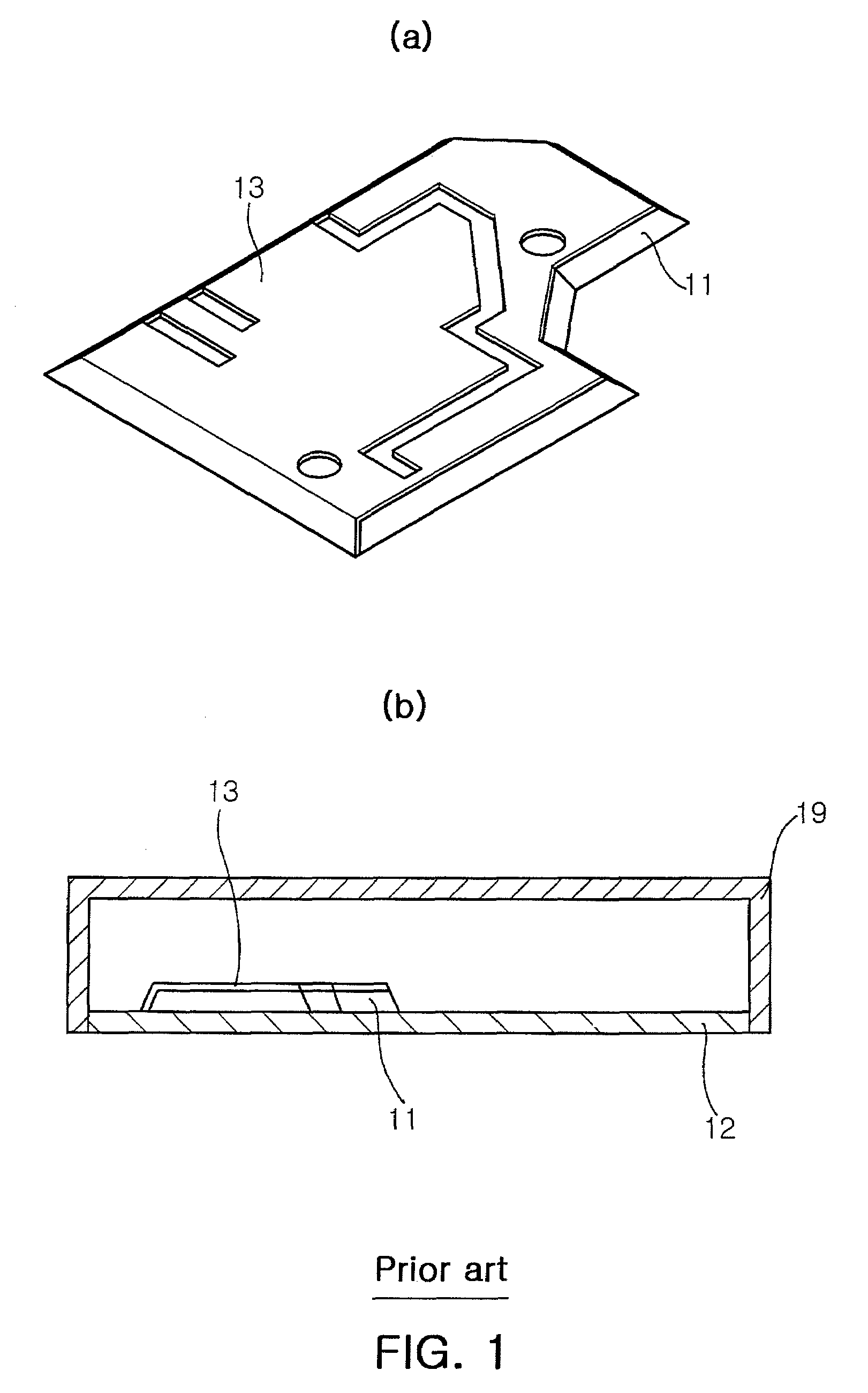
In general, among the antennas of the mobile communication terminals, external type antennas such as a rod antenna and a helical antenna are protruded in a predetermined length out of the terminal, hindering miniaturization and portability of the terminal.
In addition, when the mobile communication terminal is dropped, this type of antenna is more likely to be destructed.
On the contrary, built-in antennas mounted inside mobile communication terminals have reduced risk of destruction, but miniaturization can also be a problem due to their physical size.
However, this method limits miniaturization as the antenna requires a space to be mounted inside the mobile communication terminal.
Therefore, the antenna pattern should be printed using a low-temperature paste, thus limiting selection of the material because the paste should be selected in consideration of printability, adhesive property, etc.
The base of the antenna is made of a polymer-based material, hindering high temperature treatment, and as a result, the organic substances contained in the conductive ink remain even after the antenna radiator is formed.
This results in low electric conductivity of the antenna radiator, problematically degrading the radiation characteristics of the antenna.

Method used


Image

  • Film type antenna and mobile communication terminal case using the same
  • Film type antenna and mobile communication terminal case using the same
  • Film type antenna and mobile communication terminal case using the same

Examples


Embodiment Construction

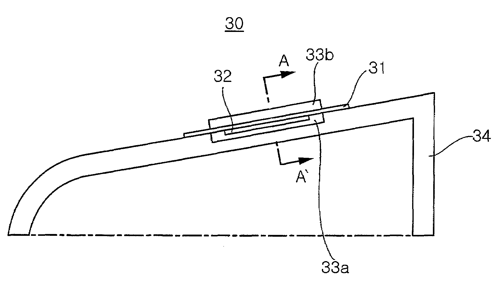
[0031]Exemplary embodiments of the present invention will now be described in detail with reference to the accompanying drawings.

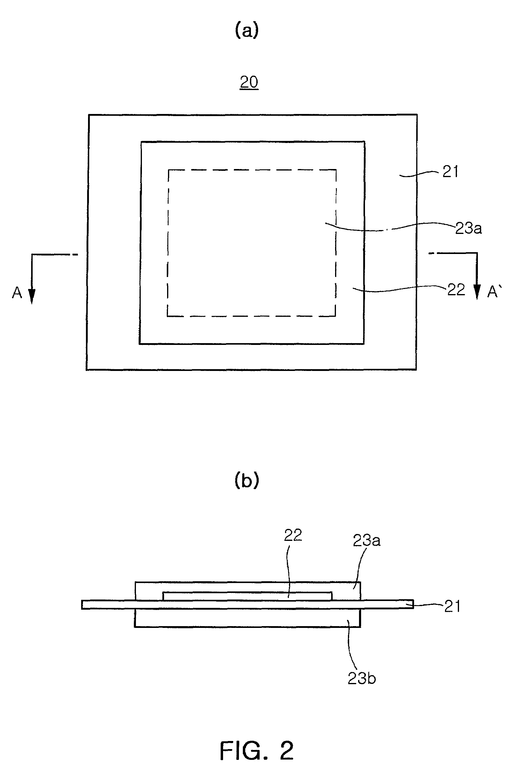
[0032]FIGS. 2(a) and 2(b) are a plan view and a sectional view, respectively, illustrating a film type antenna according to an exemplary embodiment of the present invention.

[0033]Referring to FIGS. 2(a) and 2(b), the film type antenna according to an embodiment of the present invention includes a carrier film 21 having first and second faces defining a thickness therebetween, a radiator 22 formed on the first face of the carrier film 21, a first protective layer 23a formed on the first face of the carrier film 21 and a second protective layer 23b formed on the second face of the carrier film 21.

[0034]The carrier film 21 can be made of a thin insulation polymer material. The carrier film can be made by selecting a material suitable for In-molding Labeling (IML).

[0035]More specifically, the carrier film with the radiator and the first and second protective l...


PUM

PropertyMeasurementUnit
thicknessaaaaaaaaaa
conductiveaaaaaaaaaa
coloraaaaaaaaaa

Abstract

A film antenna includes a carrier film made of an insulation material, a conductive radiator formed on a surface of the carrier film, and a first protective layer covering the radiator on the surface of the carrier film. The first protective layer contains a material obstructing X-ray transmission.

Description

CLAIM OF PRIORITY[0001]This application claims the benefit of Korean Patent Application No. 2007-0000277 filed on Jan. 2, 2007, in the Korean Intellectual Property Office, the disclosure of which is incorporated herein by reference.BACKGROUND OF THE INVENTION[0002]1. Field of the Invention[0003]The present invention relates to a film type antenna and, more particularly, to a film type antenna integrated with a mobile communication terminal case, and a mobile communication terminal case using the same.[0004]2. Description of the Related Art[0005]As mobile communication terminals such as GPS, PDAs, cellular phones, wireless notebook computers and the like have been widely popularized, there have been increasing demands for miniaturization. In order to meet such needs for miniaturization, the main focus has been maintaining diverse functions while reducing the volume of the mobile communication terminals. This has been especially the case for the antenna which is an essential component...

Claims


Application Information

Patent Timeline
Patent Type & Authority Patents(United States)
IPC IPC(8): H01Q1/38H01Q1/24H01P11/00H01Q1/40H04B1/38H04M1/02
CPCH01Q1/002H01Q1/242H01Q1/40H01Q1/38Y10T29/49016H01Q1/243H04M1/02H04M1/026
Inventor HONG, HA RYONG
Owner SAMSUNG ELECTRO MECHANICS CO LTD
Learn More