
Signal detecting frequency counter

a frequency counter and signal technology, applied in the field of signal detection frequency counters, can solve the problems of inability to determine the frequency of these transmissions, awkward use, receivers cannot tune to monitor, etc., and achieve the effect of accurate and rapid determination

Inactive Publication Date: 2009-06-16
COUNTER TECH
View PDF24 Cites 6 Cited by
  • Summary
  • Abstract
  • Description
  • Claims
  • Application Information

AI Technical Summary

Benefits of technology

"The invention provides a frequency determining apparatus and method for quickly and accurately determining the frequency of a received radio frequency signal. This allows for automatic tuning of a radio receiver to a channel, without the need for manual adjustment. The apparatus includes a counter for counting zero amplitude transitions of the radio frequency signal in each of a plurality of time periods, and a memory for storing frequency information for channels allocated to mobile transmitters and frequency offsets between mobile transmitters and repeater transmitters. The apparatus can be integrated into a radio receiver and can be used in conjunction with a frequency agile radio. The technical effects of the invention include improved speed and accuracy in determining the frequency of a radio signal, and improved automation and efficiency in tuning a radio receiver to a specific channel."

Problems solved by technology

The typical receiver is incapable of determining the frequencies of these transmissions so the receiver cannot tune to monitor them.
Some prior art frequency counters for tuning radio receivers have been available in housings separate from the receivers and connected to the receivers by cables, making use awkward.
Counting of the frequency and tuning of the associated receiver are disadvantageously slow because the special purpose counters require at least two complete frequency determinations before producing an output.

Method used


Image

  • Signal detecting frequency counter
  • Signal detecting frequency counter
  • Signal detecting frequency counter

Examples


Embodiment Construction

Radio Receiver with Frequency Determination

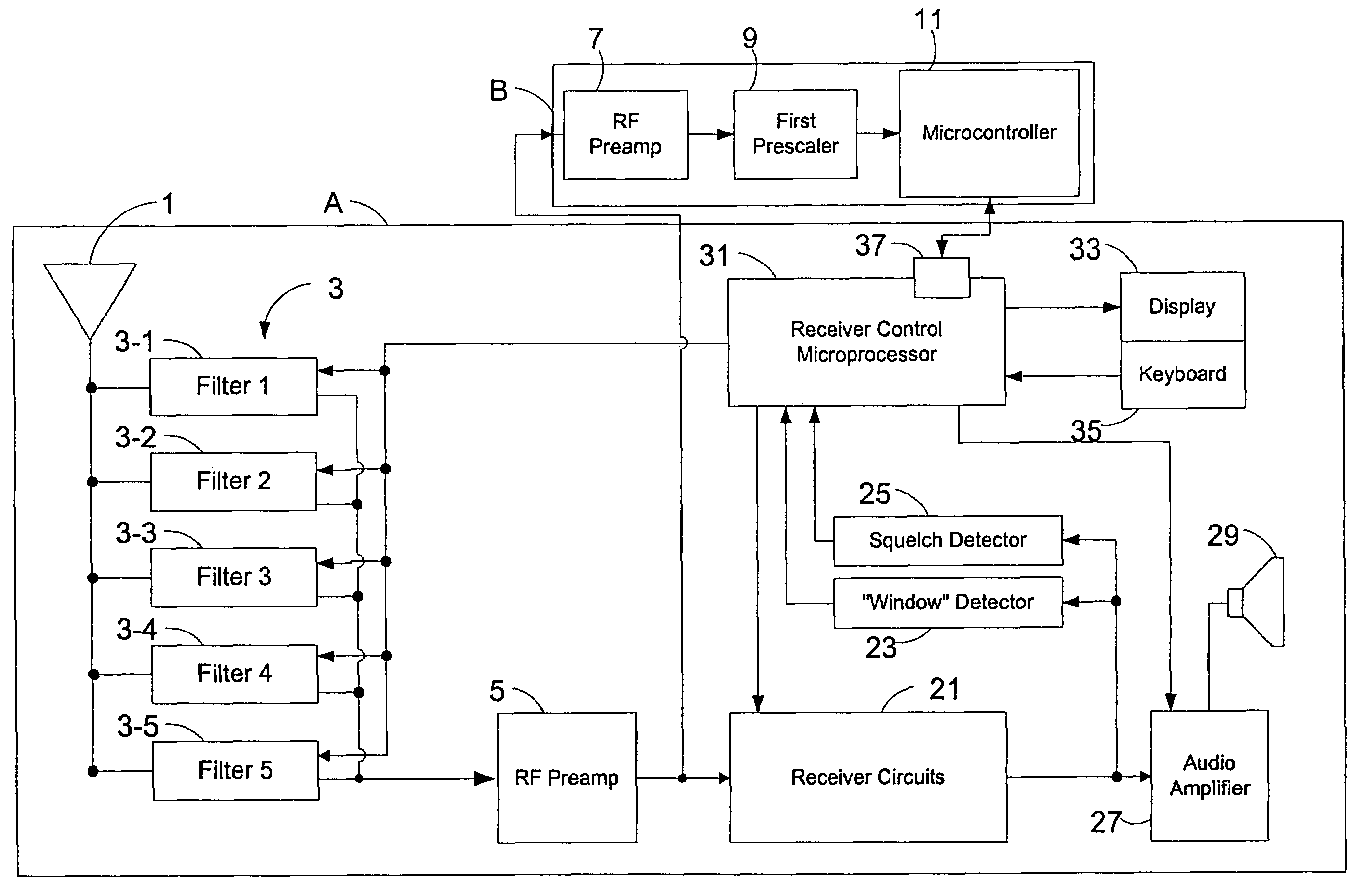
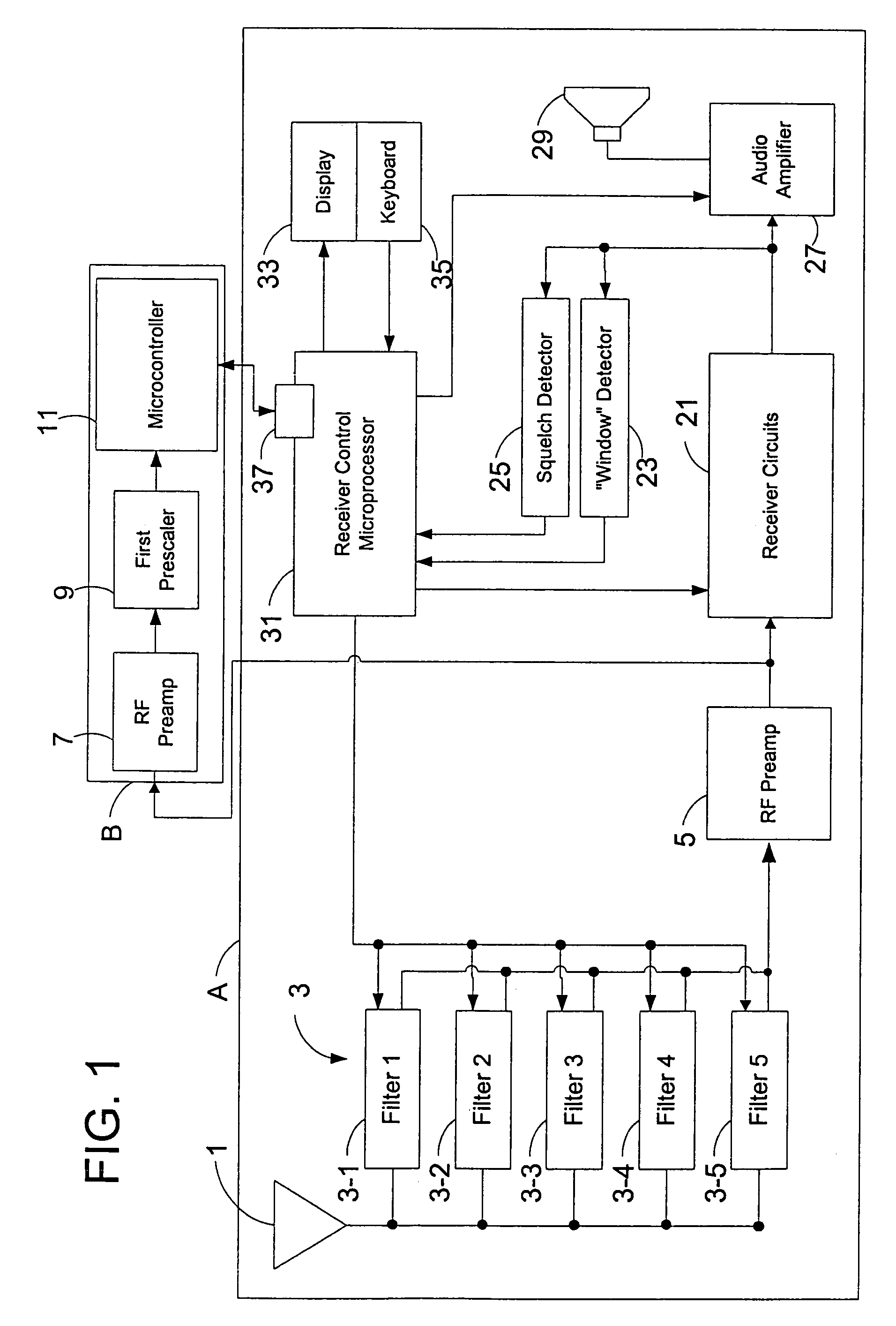
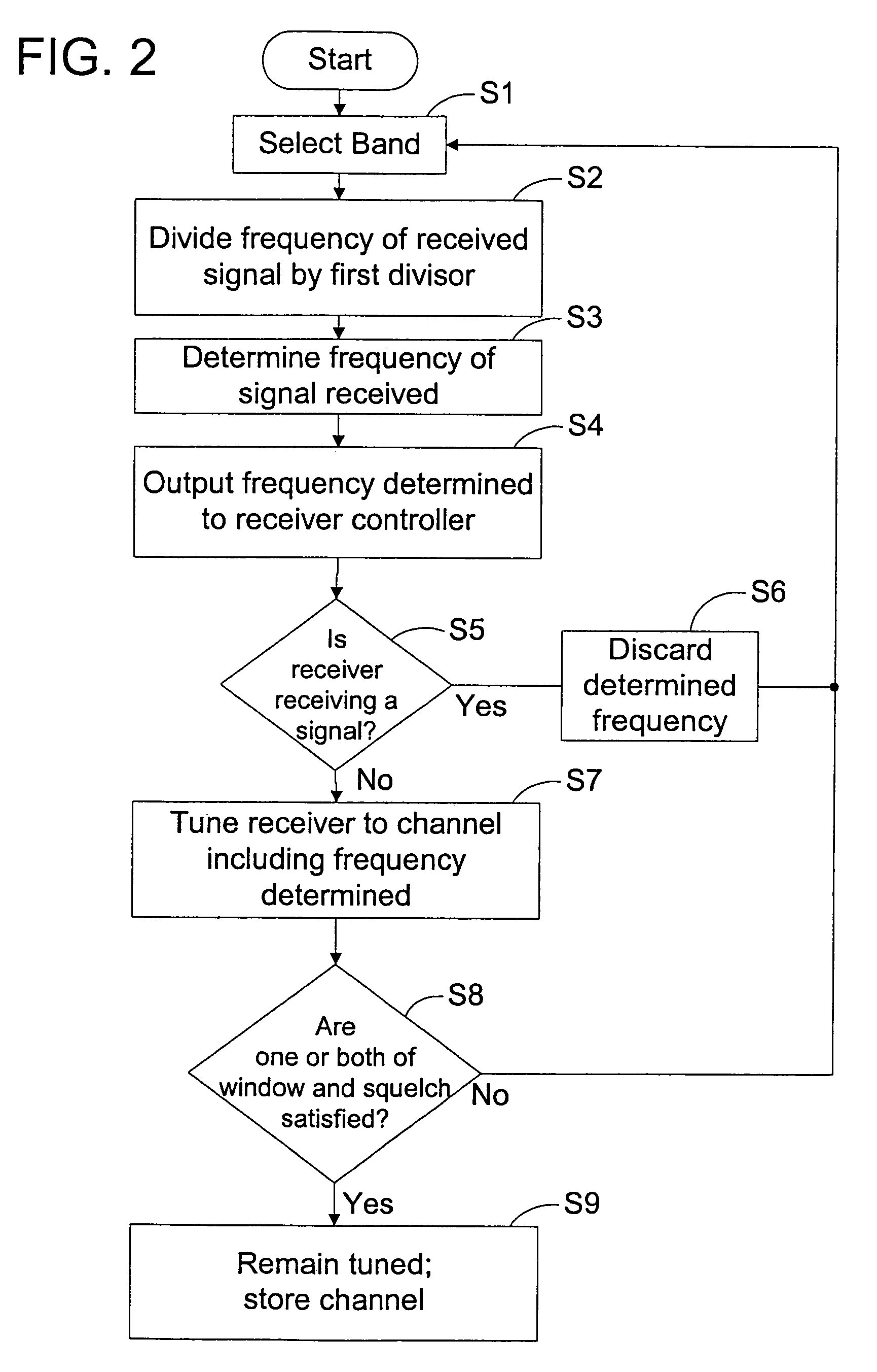
[0024]FIG. 1 is a block diagram of a frequency agile radio apparatus including an apparatus for determining the frequency of a radio frequency signal according to an embodiment of the invention. FIG. 2 is a flow chart illustrating a method of operation of radio receiver apparatus like that of FIG. 1 according to an embodiment of the invention. FIG. 3 is a flow chart illustrating the frequency determination method and apparatus exemplified by FIGS. 1 and 2. In the following description, emphasis is placed upon use of the invention in connection with a frequency agile receiver that receives radio frequency signals. However, the invention has several aspects and is not limited to application in radio receivers. For example, the frequency determination aspect of the invention may be generally applied to any frequency determination of a radio frequency signal, for example, through a directly connected circuit, without the reception of electromag...


PUM


Abstract

The invention provides an apparatus and a method for determining the frequency of a radio frequency signal. The coherency of a received signal is determined and only the frequency of a coherent signal is determined. Zero amplitude transitions of coherent signals are counted in respective time periods. If the counts in each time period agree within a quantization error, the accumulated counts for a fixed time period are employed to determine a frequency. The frequency determining apparatus and method are particularly useful with a frequency agile radio receiver for detecting the presence of radio frequency signals from nearby mobile and stationary transmitters. Upon determination of the frequency of the nearby transmitter, the channel of transmission can be determined from a memory within the receiver and the receiver can be tuned to monitor the transmission. Additional tests to verify the frequency determination may be applied using squelch and window detector circuits of the radio receiver.

Description

[0001]This application is a continuation of U.S. patent application Ser. No. 09 / 860,506 filed May 21, 2001, now U.S. Pat. No. 7,006,797.FIELD OF THE INVENTION[0002]The invention concerns an apparatus for determining the frequency of a received coherent radio frequency signal and a process for determining the frequency of a coherent radio frequency signal. The apparatus and process are particularly useful in radio equipment, such as frequency agile radio receivers and transceivers. The apparatus and method may identify a channel including the frequency determined for automatically tuning the radio receiver or transceiver to the channel including the radio frequency signal. By automatically tuning the receiver or transceiver, a transmission can be monitored or a conversation in progress can be joined.BACKGROUND[0003]Apparatus for determining the frequency of an electrical signal has long been known. A conventional apparatus for determining the frequency is usually referred to as a fre...

Claims


Application Information

Patent Timeline
Patent Type & Authority Patents(United States)
IPC IPC(8): H04B1/18H04B17/00
CPCH04B1/1027
Inventor SULLIVAN, TERENCE SEANBRENNAN, TERENCE
Owner COUNTER TECH
Learn More