Methods for picking and placing workpieces into small form factor hard disk drives

a technology of hard disk drives and workpieces, applied in the direction of metal-working machine components, measurement/indication equipment, metal-working apparatus, etc., can solve the problems of difficult to pick up screws, cross-thread holes, and many of the constituent components of drives are too small to be consistently produced

Inactive Publication Date: 2009-06-23
WESTERN DIGITAL TECH INC
View PDF12 Cites 71 Cited by
  • Summary
  • Abstract
  • Description
  • Claims
  • Application Information

AI Technical Summary

Benefits of technology

[0011]According to another embodiment, the present invention is a robotic screw driver station for driving screws into a threaded hole. The robotic screw driver may include a screw driver configured to engage and drive a screw, a servo motor assembly configured to move the screw driver and the engaged screw, a machine vision assembly configured to capture an image of the threaded hole, and a ...

Problems solved by technology

As a result of such continuing miniaturization, many of the constituent components of the drives have become too small to be consistently, speedily and reliably handled by human hands.
These screws are difficult to pick up, couple to a screw driver and drive into a selected threaded hole in a disk drive.
Often, such small screws are accidentally driven at an angle into the threaded hole, which may cross-thread the hole and damage the drive.
Moreover, as the screws and corresponding holes are so small, manual over-torquing of the screws is also a problem.
Even when such small screws are correctly aligned with their intended threaded hole and correctly driven therein, human operators are slow and cannot reliably repeat such precision movements for any extended length of time.
Moreover, it has proven to be difficult to manually tighten and loosen these micro screws without breaking them.
Thus, broken screws and particulate con...

Method used


Image

  • Methods for picking and placing workpieces into small form factor hard disk drives
  • Methods for picking and placing workpieces into small form factor hard disk drives
  • Methods for picking and placing workpieces into small form factor hard disk drives

Examples


Embodiment Construction

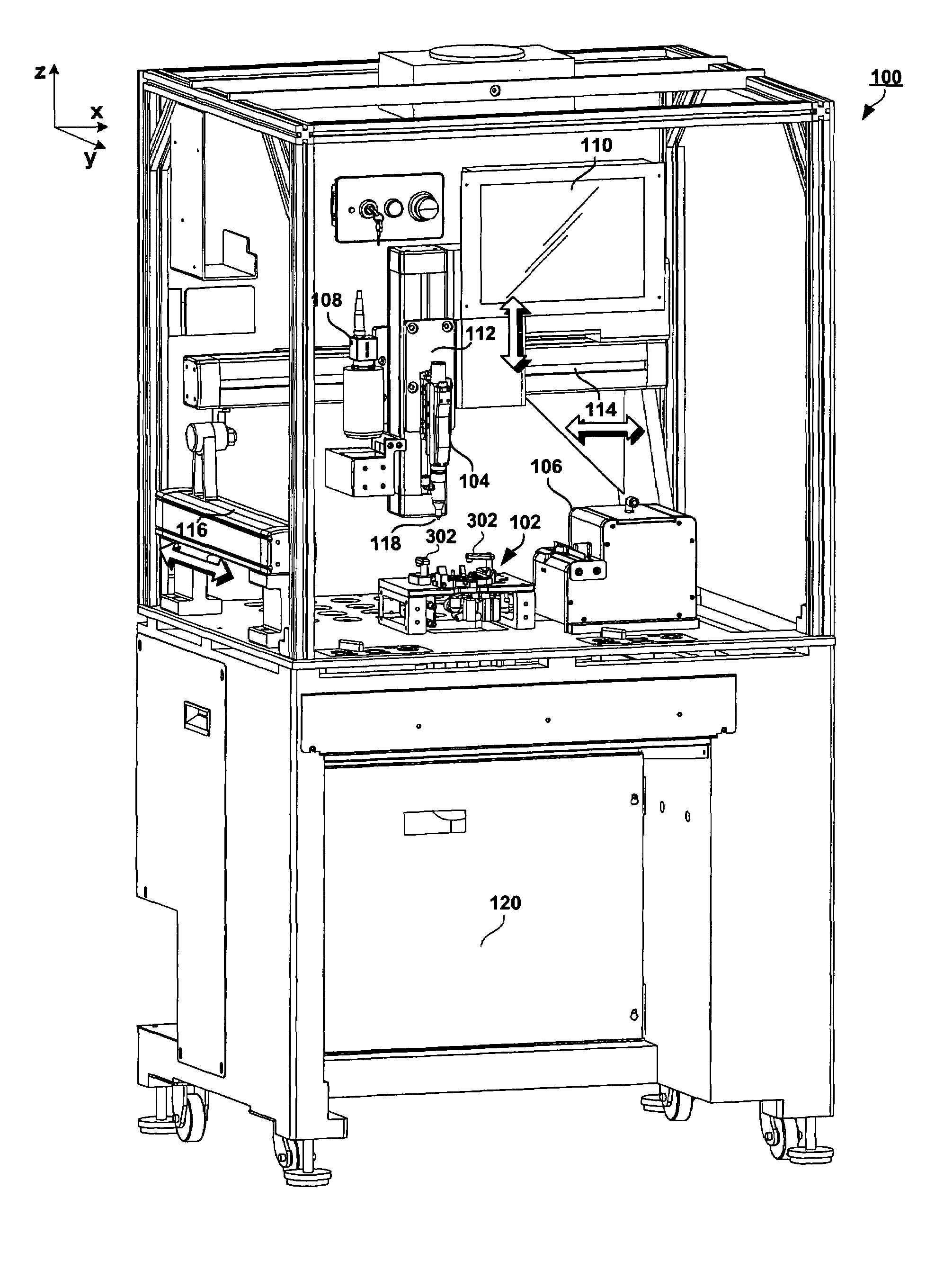
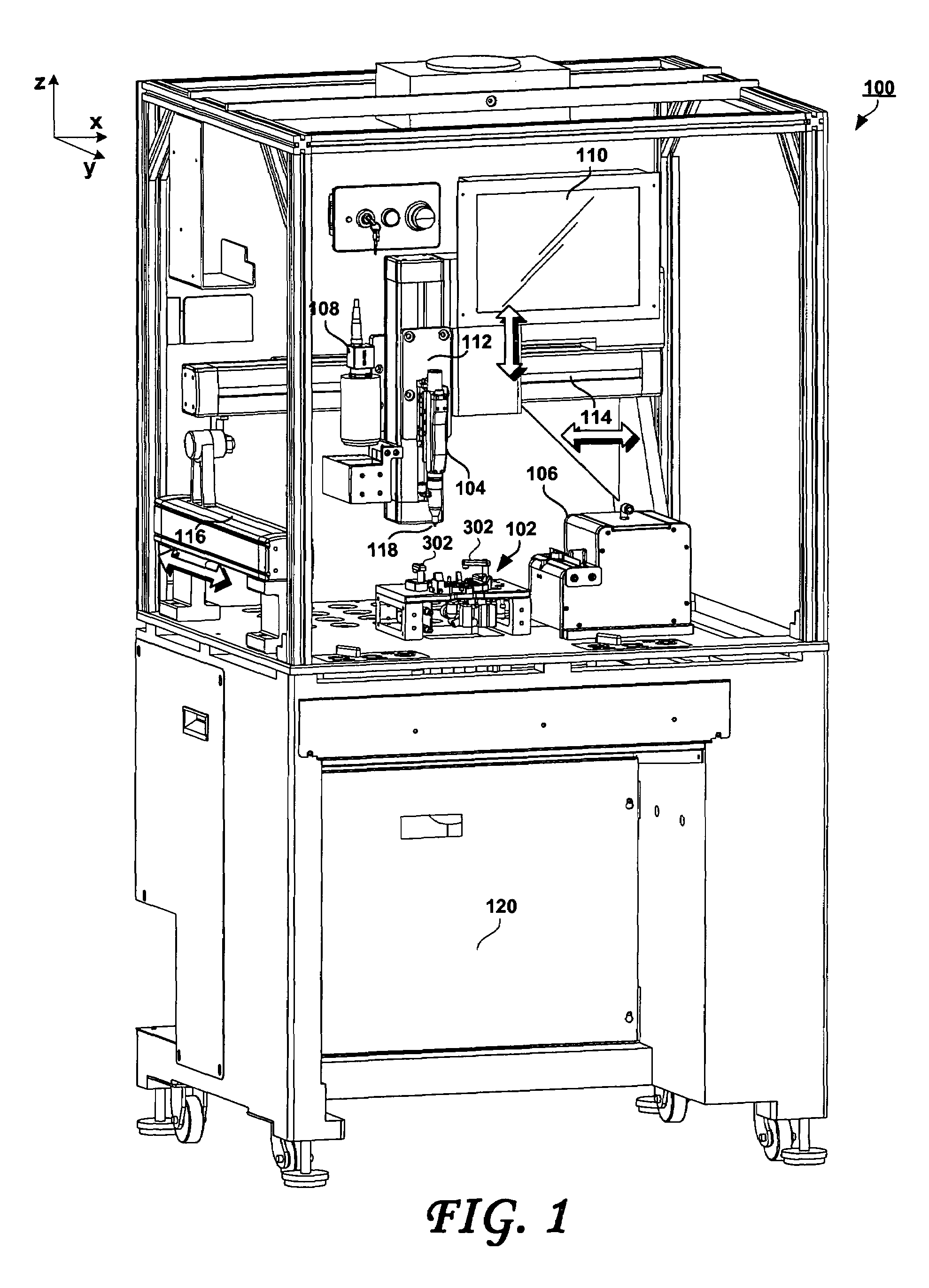
[0023]FIG. 1 shows a robotic station 100 for picking and placing workpieces into small form factor hard disk drives, according to an embodiment of the present invention. FIG. 2 is a detail view of a portion of the robotic station of FIG. 1, and FIG. 3 is a top view of a portion of the pick and place station of FIGS. 2 and 3. A number of cover panels have been removed in these views, to allow further detail to be shown. The workpieces that may be picked and placed using embodiments of the present invention may include, for example, screws or other fasteners, ramp load and latch assemblies, head stack assemblies and the like. Considering now FIGS. 1, 2 and 3 collectively and according to an embodiment in which the workpiece are screws or similar fasteners, the robotic station 100 may include an electric screw driver 104 that is commercially available, for example from Microtec Systems GmbH of Germany. One of the tasks of the screw driver 104 is to torque the miniature screws used in t...


PUM

PropertyMeasurementUnit
Vacuumaaaaaaaaaa
Torqueaaaaaaaaaa

Abstract

A method of driving screws may include steps of providing a robotically controlled screw driver, a servo motor assembly for moving the screw driver, at least one controller for controlling the screw driver and the servo motor assembly, and a machine vision assembly coupled to the controller. The screw may be coupled to the screw driver, and the screw may be aligned with a threaded hole using the machine vision assembly and the controller to control the servo motor assembly, such that the screw is aligned with a center of the threaded hole. The aligned screw may then be driven into the threaded hole.

Description

BACKGROUND OF THE INVENTION[0001]1. Field of the Invention[0002]The present invention relates generally to the field of disk drive manufacturing. In particular, embodiments of the present invention are drawn to robotic machines for picking and placing workpieces such as screws on selected features of a hard disk drive being manufactured.[0003]2. Description of the Prior Art[0004]A typical hard disk drive includes a head disk assembly (“HDA”) and a printed circuit board assembly (“PCBA”). The HDA includes at least one magnetic disk (“disk”), a spindle motor for rotating the disk, and a head stack assembly (“HSA”) that includes a slider with at least one transducer or read / write element for reading and writing data. The HSA is controllably positioned by a servo system in order to read or write information from or to particular tracks on the disk. The typical HSA has three primary portions: (1) an actuator assembly that moves in response to the servo control system; (2) a head gimbal a...

Claims


Application Information

Patent Timeline
IPC IPC(8): B23Q17/00
CPCB23P19/007B23P19/06B23P19/066B23P19/10Y10T29/49027Y10T29/49766Y10T29/49769Y10T29/49025
Inventor VANGAL-RAMAMURTHY, JAMBUNATHANBUTLER, WALTER W.
Owner WESTERN DIGITAL TECH INC
Why Eureka
Try Eureka