Concentric machining device for a roller

a machining device and roller technology, applied in the direction of dough shaping, manufacturing tools, shaping tools, etc., can solve the problems of high defective rate, easy to hurt the outer surface of the roller, and difficult to control the precision of the coaxial line, so as to promote the production rate of the roller and enhance the precision of concentricity

Inactive Publication Date: 2009-06-23
HUANG TE LI
View PDF1 Cites 4 Cited by
  • Summary
  • Abstract
  • Description
  • Claims
  • Application Information

AI Technical Summary

Benefits of technology

[0016]An object of the present invention is to provide a concentric machining device with which a roller can be machined, squeezed and formed accurately at the same time to ensure concentricity of the entire roller.
[0018]A further object is to provide a concentric machining device with which production rate of the roller can be promoted and precision for concentricity can be enhanced to 90% more than that made with the conventional way.

Problems solved by technology

1. The journal 12 at the two ends 11 has to be machined individually such that twice works for clamping and unloading the roller 10 have to be done during machining.
2. Due to twice works for machining the journal 12 at the two ends 11 being done, it is time wasting and it is not easy to control precision of the coaxial line such that defective rate is high.
3. It is easy to hurt the outer surface of the roller 10 being clamped and unloaded several times.
4. The inner wall of the roller 10 is incapable of being lathe-worked except the two ends 11, it is incapable of obtaining a homogeneous thickness of the roller 10 and correction of concentricity leads to high production cost and difficult work such that experienced professional is required.
5. A sufficient thickness of the blank roller has to be retained for cutting and machining such that costs related to material, delivery and machining are hard to reduce substantially.
6. It is complicated to perform machining for the roller so that speed of machining is slow and more material has to be wasted.

Method used


Image

  • Concentric machining device for a roller
  • Concentric machining device for a roller
  • Concentric machining device for a roller

Examples


Embodiment Construction

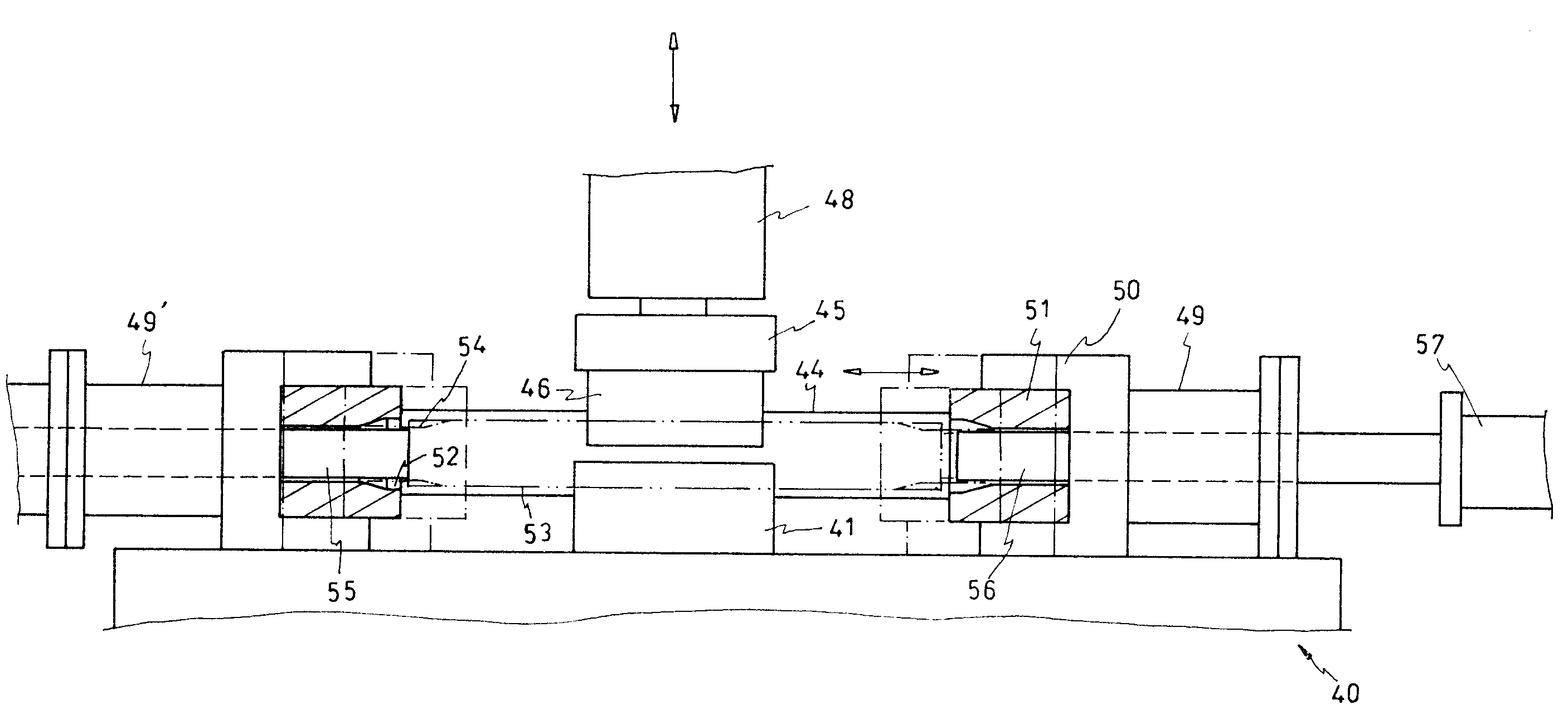
[0025]Referring to FIGS. 4 and 5, a concentric machining device 40, which is associated with a squeezing and forming machine, according to the present invention provides a lower base 41 in which a lower mold 42 is received. The lower mold 42 has a lower locating recess 43. An upper base 45 is disposed to face the lower base 41 and an upper mold tool 46 with an upper locating recess 47 is attached to the bottom of the upper base 45. The lower locating recess 43 is opposite to the upper locating recess 47 for locating a roller 53, which is indicated with dash lines. The upper base 45 is fixedly attached to an end of a hydraulic cylinder 48 and is actuated by the hydraulic cylinder 48 to set the roller 53 in place tightly for both ends of the roller 53 being capable of being subjected to impacts while squeezing and forming work is performed. The lower base 41 at two lateral sides provides a guide rod 44 respectively next to the lower mold tool 42. Both ends of the respective guide rod ...


PUM

PropertyMeasurementUnit
thicknessaaaaaaaaaa
speedaaaaaaaaaa
diameteraaaaaaaaaa

Abstract

A concentric machining device for a roller includes a movable upper base, a stationary lower base, two movable mold seats, two slide rods and four first hydraulic cylinders. Each of the mold seats has a forming mold inside, the forming mold has a fitting hole with an enlarged conical opening at the front side thereof, a locating shaft is received in the forming mold of the first mold seat and penetrates the fitting hole thereof and the first cylinder member, a clamping shaft is received in the forming mold of the second mold seat and penetrates the fitting hole thereof and the second hydraulic cylinder to connect with the fourth hydraulic cylinder. The roller is held by the bases and the shafts via two of the hydraulic cylinders and both ends of the roller are machined by the forming molds in the mold seats to provide squeezed and shrunk shapes once the mold seats are actuated by the other two hydraulic cylinders.

Description

BACKGROUND OF THE INVENTION[0001]1. Field of the Invention[0002]The present invention is related to a hydraulic squeezing and shrinking machine for forming ends of a roller and particularly to a concentric machining device for ends of a roller.[0003]2. Brief Description of Related Art[0004]Referring to FIG. 1, a conventional machining and forming device for a roller usually provides a cylindrical blank roller 10 with a sufficient thickness available for being cut and worked. Then, the blank roller 10 is worked to provide a smooth outer surface with two conical ends 11 for a transmission belt such as a pedaling belt of a running machine moving on the roller 10 steadily without deviating leftward or rightward. The conical ends 11 are made a concentric bore as a journal 12 respectively with a lathe machine for a bearing 13 being mounted to the journal 12 such that the roller 10 is capable of turning smoothly. A spindle 14 is arranged in the center of the roller 10 to fit with the beari...

Claims


Application Information

Patent Timeline
Patent Type & Authority Patents(United States)
IPC IPC(8): B21D41/04B21D53/00
CPCB21D37/20B21D41/04Y10T29/49544
Inventor HUANG, TE-LI
Owner HUANG TE LI
Why Eureka
Try Eureka