
Coil for coolant circulation, method for making same and reactor comprising same

a coolant fluid and coil technology, applied in the direction of rotary stirring mixers, indirect heat exchangers, lighting and heating apparatus, etc., can solve the problem of relatively small pressure drop that they generate, and achieve the effect of good recirculation of reaction medium

Inactive Publication Date: 2009-06-23
PERFORMANCE POLYAMIDES SAS
View PDF10 Cites 9 Cited by
  • Summary
  • Abstract
  • Description
  • Claims
  • Application Information

AI Technical Summary

Benefits of technology

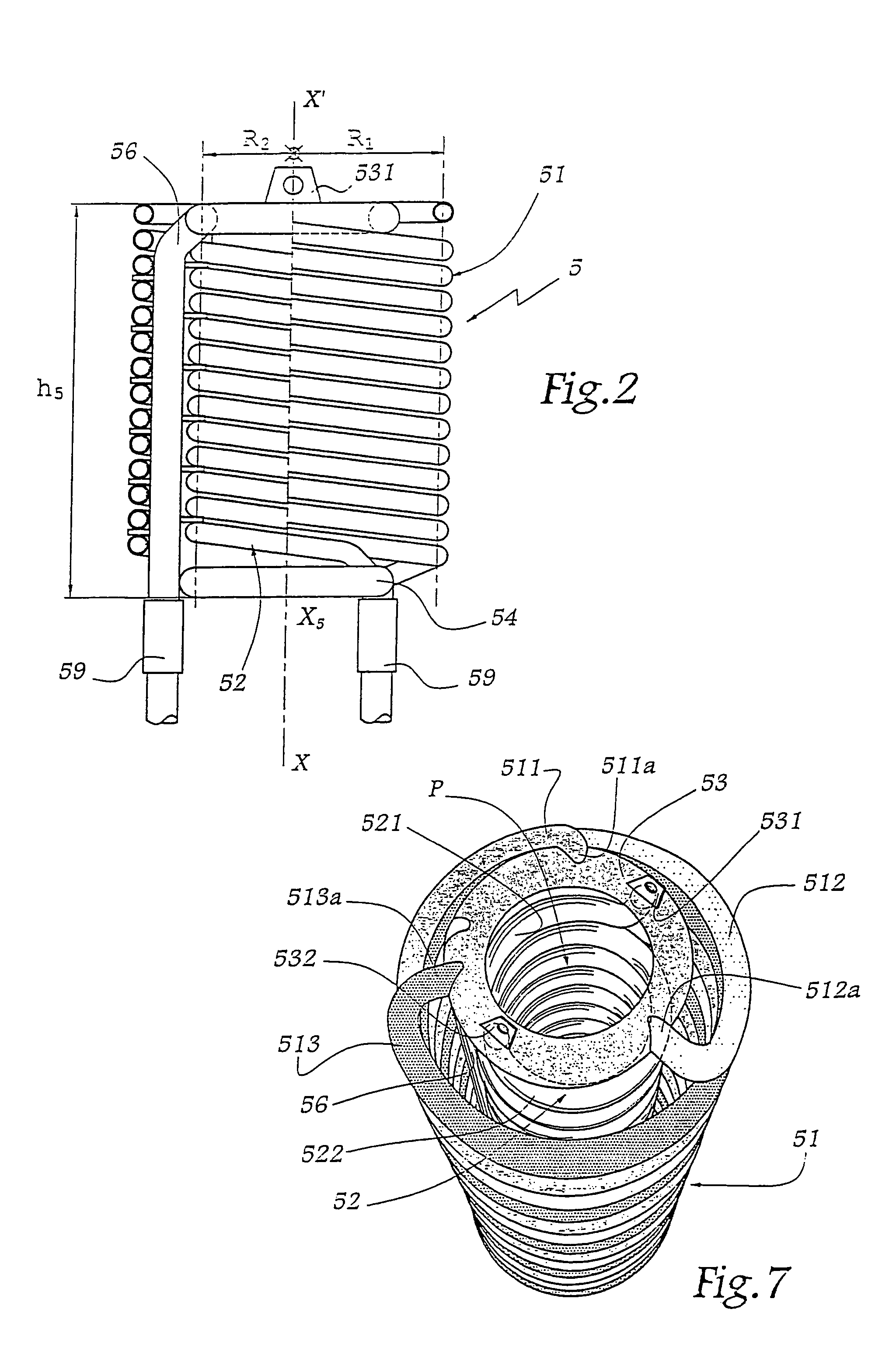
[0010]Thanks to the use of two nested helical tube segments, it is possible that these segments each have a relatively short length, with the result that the pressure drop that they generate is relatively slight, even if the cross-section of the tube used may also be small. In addition, the fact that the helical tube segments have a relatively short length induces a relatively considerable slope thereof, i.e. greater than in the case of a single circular segment extending over the whole height of the coil. In this way, in the case of the coolant fluid being supplied in vapour phase able to condense in the tubes, the flow of the condensed fluid in these segments is more rapid, hence less risk of accumulation of condensates and less space requirement for liquid. The fact that these segments form a cylindrical bundle avoids their significantly disturbing the flow or re-circulation of the reaction medium in the central part of a reactor.
[0021]According to another aspect of the invention, the inner bundle or the single bundle of the coil forms a central well of radius included between 20 and 70% of the radius of the vessel, which allows a good re-circulation of the reaction medium in the vessel. In the case of a coil with two bundles, the central well formed by the inner bundle preferably has a radius included between 20 and 40% of the radius of the vessel.

Problems solved by technology

Thanks to the use of two nested helical tube segments, it is possible that these segments each have a relatively short length, with the result that the pressure drop that they generate is relatively slight, even if the cross-section of the tube used may also be small.

Method used


Image

  • Coil for coolant circulation, method for making same and reactor comprising same
  • Coil for coolant circulation, method for making same and reactor comprising same
  • Coil for coolant circulation, method for making same and reactor comprising same

Examples


Embodiment Construction

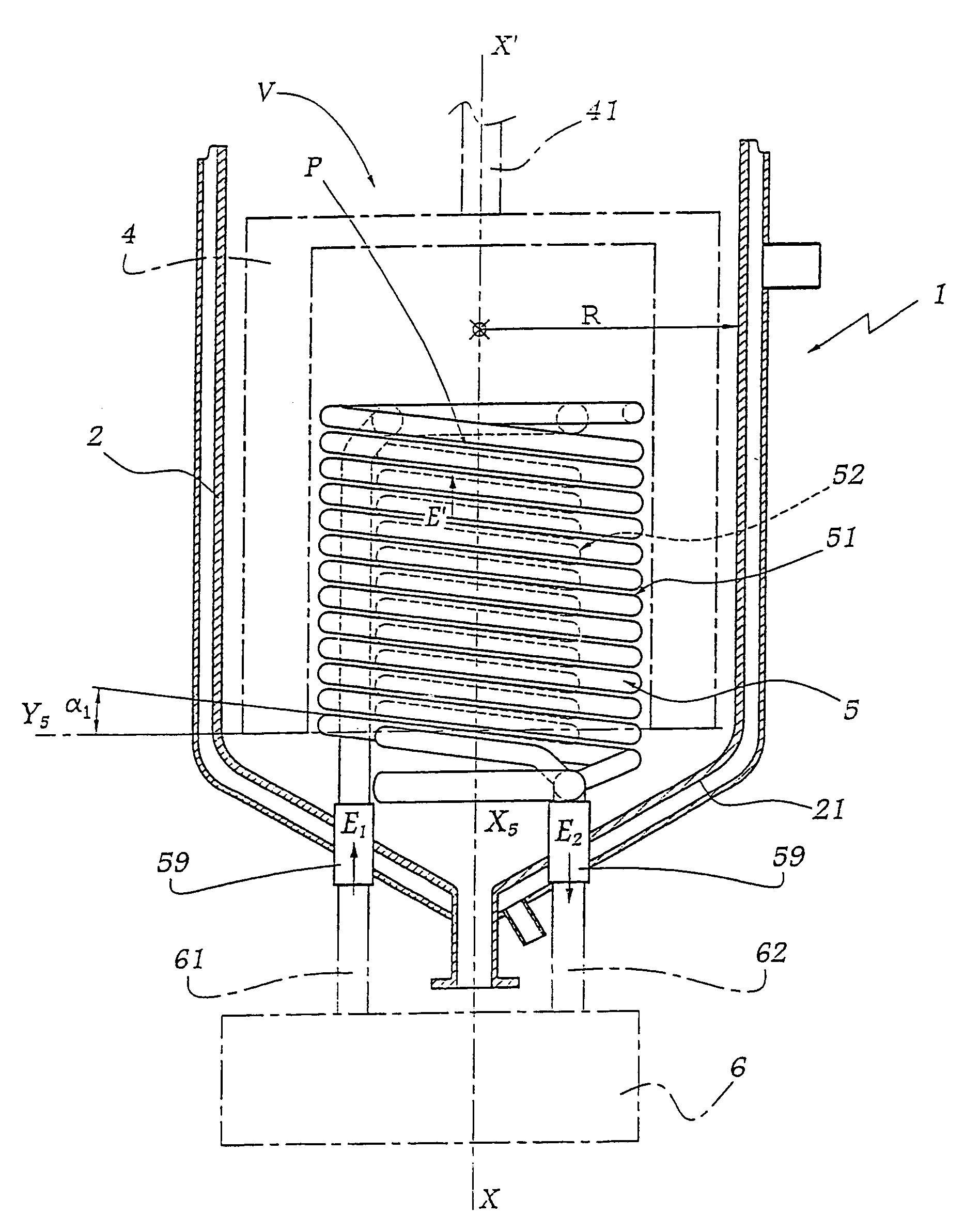
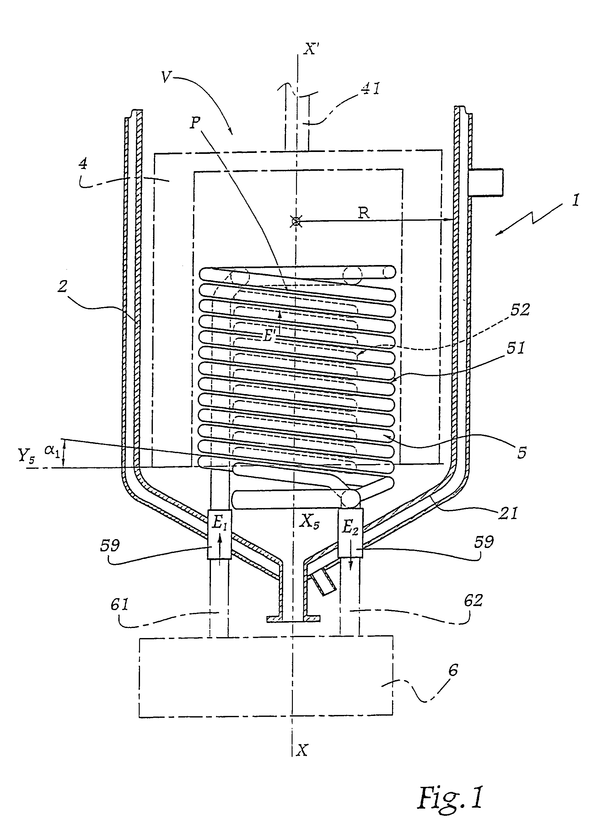
[0031]The reactor 1 shown in FIG. 1 is used for the polymerization of polyamide. It has a volume V of the order of 11 m3. This reactor 1 comprises a vessel 2 of substantially cylindrical shape with a substantially truncated bottom 21. A cover (not shown) is provided to be mounted on the vessel 2 in order to constitute the ceiling thereof and to ensure seal of the interior volume V of the reactor 1 with respect to the ambient medium.

[0032]An agitator 4 is provided in the volume V. It is driven by a shaft 41 aligned on a central axis X-X′ of the reactor and passing through the cover. The agitator 4 comprises substantially helical blades mounted on a cage which surrounds a coil 5. In order to render the drawing clearer, the agitator 4 is silhouetted in dashed and dotted lines solely in FIG. 1.

[0033]Other forms of agitators may be envisaged, as long as they are compatible with the space available in the volume V.

[0034]The vessel 2 is of double envelope type in order to allow the circula...


PUM


Abstract

This invention relates to a coil comprising a first helical tube segment (511) and a second helical tube segment (512, 513) extending, parallel to the first helical segment (511), between a distributor (53) and a manifold (54), said first and second helical segments (511, 512, 513) being centred on a common geometrical axis (X5), with substantially the same bending radius (R1) and nested, such that they form together a globally cylindrical bundle (51). The method comprises a step which consists in interleaving the helical tube segments (511-513) so as to form a globally cylindrical bundle. The invention also concerns a reactor equipped with such a coil which can be used for treating a viscous medium or for carrying out chemical reactions, such as 6-6 polyamide polymerization.

Description

[0001]This application is an application under 35 U.S.C. Section 371 of International Application Number PCT / FR03 / 00177 filed on Jan. 20, 2003.BACKGROUND OF THE INVENTION[0002]The present invention relates to a coil for circulation of coolant fluid and to a method for manufacturing such a coil. The invention also concerns a reactor for the treatment of a viscous medium or for carrying out chemical reactions in a viscous medium, such as a polymerization, such a reactor comprising such a coil. Finally, the invention concerns the use of such a reactor.[0003]It is known to effect polymerization of polyamide continuously or discontinuously. In the so-called discontinuous methods, one proceeds by batches with reactors of autoclave type. In that case, it is known to evaporate the water of an aqueous solution of two monomers and the water produced by their polymerization, thanks to an outside heat supply.[0004]Such heat supply must be sufficient for the reaction of polymerization to take pl...

Claims


Application Information

Patent Timeline
IPC IPC(8): F28F9/26F28D7/02F28F1/00B01F7/16B01F15/06B01J19/00B01J19/18C08F2/01F28D1/047F28D1/06F28D7/00
CPCB01J19/0013B01J19/18F28D7/024B01J2219/00083B01J2219/00094F28D7/02B01J19/00
Inventor NURIS, THIERRYTHIERRY, JEAN-FRANCOIS
Owner PERFORMANCE POLYAMIDES SAS
Learn More