Apparatus for housing an air moving unit

a technology for air moving units and apparatuses, which is applied in the direction of electric apparatus casings/cabinets/drawers, machines/engines, liquid fuel engines, etc., can solve the problems of unnecessarily occupying space by design, water damage in the space served by the hvac system, and space utilization of such components, so as to enhance static pressure performance and efficiency, and free air flow

Inactive Publication Date: 2009-06-23
LENNOX MFG
View PDF18 Cites 29 Cited by
  • Summary
  • Abstract
  • Description
  • Claims
  • Application Information

AI Technical Summary

Benefits of technology

[0006]It is, therefore, an object of the present invention to provide an air handling unit that occupies no greater “footprint” than presently dictated by industry standards, that still passes through predetermined openings such as openings accessing attics, closets or other restricted spaces, and that permits freer air flow to enhance static pressure performance and efficiency without entraining moisture in flowing air to a serviced area

Problems solved by technology

Space utilization within such components is therefore a constraint in their design.
In some air handling units if a blower unit is placed too close to an associated evaporator unit a problem is created because condensate can be entrained in high velocity air flow from the evaporator unit through the blower unit and cause water damage in the space served by the HVAC system, such as a home or an office.
Such a design occupies space unnecessarily.
Further, the restricted air flow required by such designs contributes to lower static pressure performance and lower efficiency.

Method used


Image

  • Apparatus for housing an air moving unit
  • Apparatus for housing an air moving unit
  • Apparatus for housing an air moving unit

Examples


Embodiment Construction

[0011]The term “locus” is intended herein to indicate a place, location, locality, locale, point, position, site, spot, volume, juncture, junction or other identifiable location-related zone in one or more dimensions. A locus in a physical apparatus may include, by way of example and not by way of limitation, a corner, intersection, curve, line, area, plane, volume or a portion of any of those features. A locus in an electrical apparatus may include, by way of example and not by way of limitation, a terminal, wire, circuit, circuit trace, circuit board, wiring board, pin, connector, component, collection of components, sub-component or other identifiable location-related area in one or more dimensions.

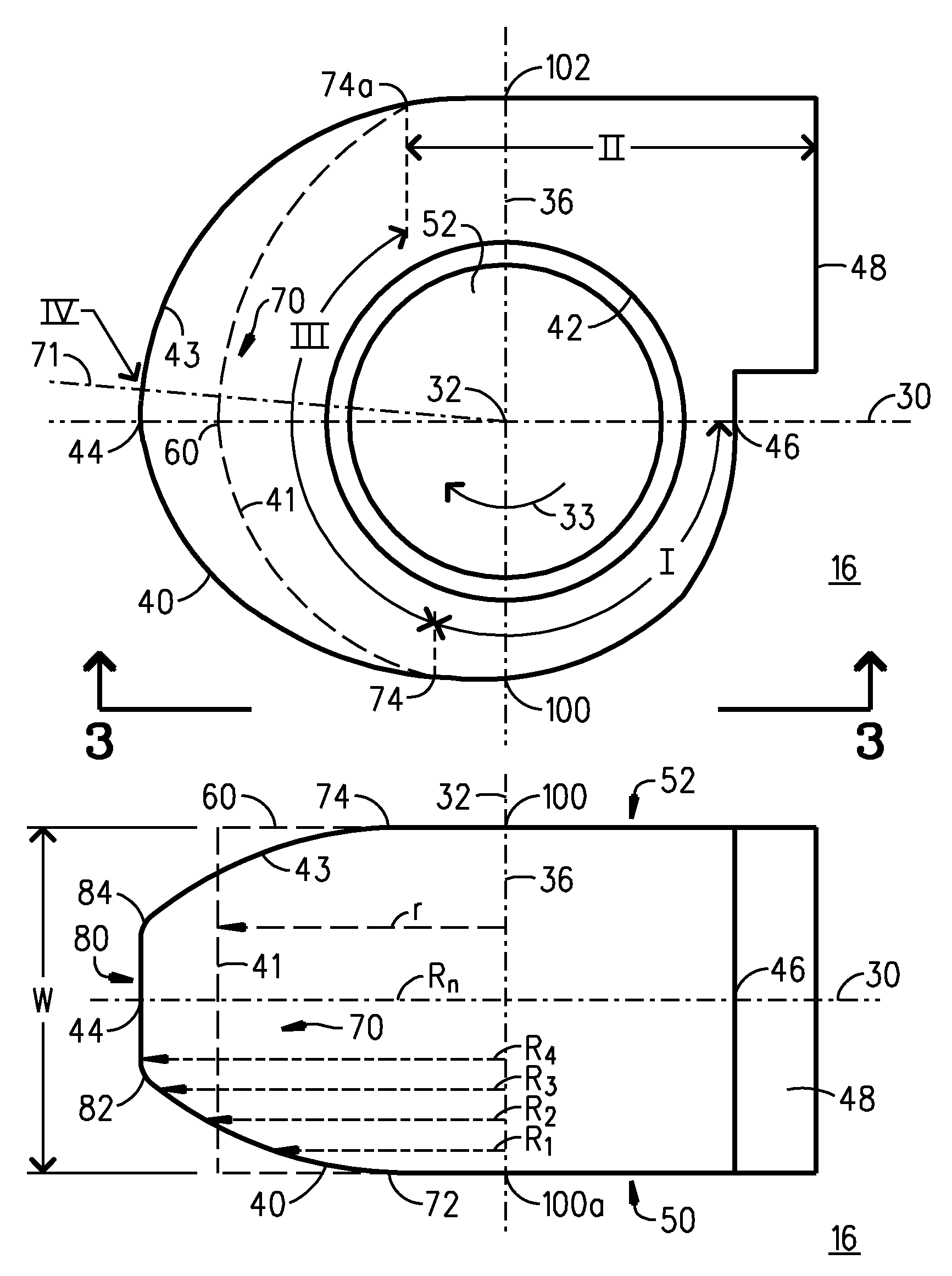
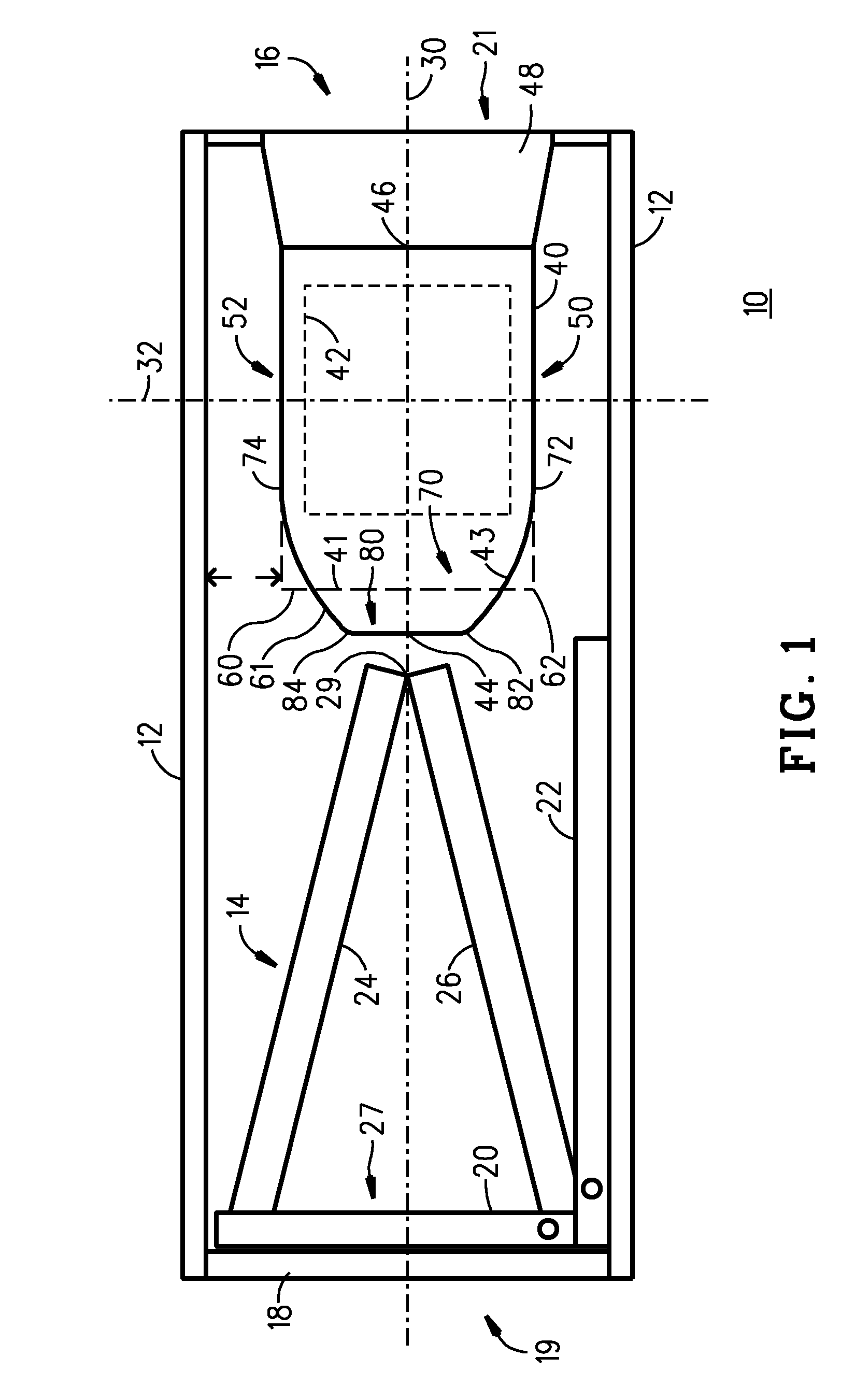
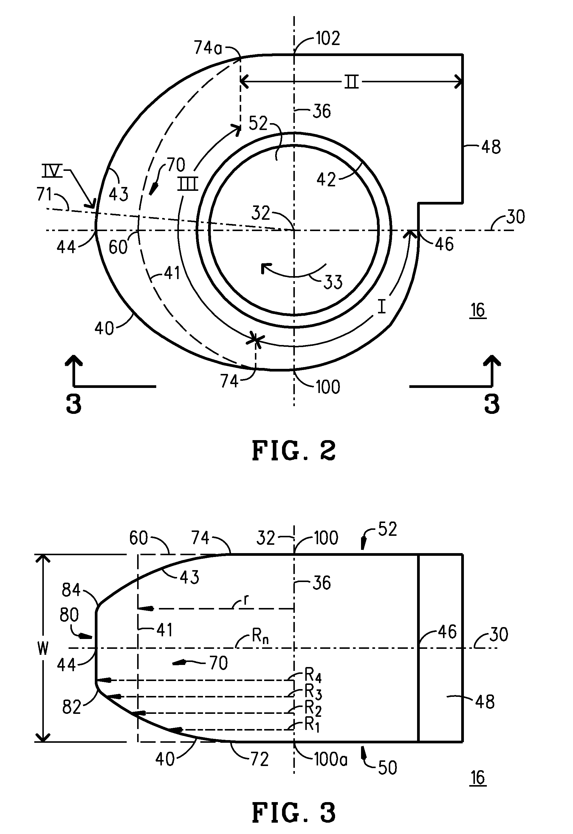
[0012]FIG. 1 is a schematic diagram of representative air handling equipment in which the present invention may be advantageously employed. In FIG. 1, a representative residential air handling unit 10 is of the sort of air handling unit appropriate, by way of example and not by way of ...


PUM


Abstract

A housing cooperates with an air mover rotating about a rotation axis to move air received from an approach to an exhaust. The approach is generally oriented about a direction intersecting the housing at upstream and downstream limits. The housing presents an interior surface establishing radii between the axis and the surface. The radii have a generally constant radial value across a width in planes containing the axis in a first zone between the downstream limit and a first locus, and in a second zone between a second locus and the exhaust. The radii vary between a smallest and a largest radius across the width in planes containing the axis in a variance zone upstream of the axis. The smallest radius is less than the radial value at the first and second loci. The largest radius is larger than the radial value at one of the first and second loci.

Description

BACKGROUND OF THE INVENTION[0001]The present invention is directed to air moving or air handling units, and especially to air handling devices in which blower housing apparatuses are contained, such as in an HVAC (Heating Ventilating Air Conditioning) system.[0002]Air handling units for HVAC systems are typically constrained in their physical dimensions to conform with predetermined industry standards. The relevant industry standards are predicated, at least in part, upon a requirement that some components of HVAC systems must be amenable to installation in a residential attic, closet or other restricted space. Such space-restricted components must, therefore, be restricted to a particular “footprint” and be passable through an access opening to the attic, closet or other restricted space. Space utilization within such components is therefore a constraint in their design. Air handling units for use in a residential HVAC system are, by way of example and not by way of limitation, amo...

Claims


Application Information

Patent Timeline
Patent Type & Authority Patents(United States)
IPC IPC(8): F04D29/54
CPCB60H1/00471F04D29/4226F04D29/601
Inventor HANSON, OVED W.HOGAN, MARK R.USELTON, ROBERT B.
Owner LENNOX MFG
Why Eureka
Try Eureka