
Chevron system for gas turbine engine

Inactive Publication Date: 2017-05-04
PRATT & WHITNEY CANADA CORP
View PDF13 Cites 0 Cited by
  • Summary
  • Abstract
  • Description
  • Claims
  • Application Information

AI Technical Summary

Benefits of technology

The patent describes a way to increase the size of a surface in a gas turbine engine of an aircraft. The method involves moving a part that can expand the surface area, and then rotating two panels that make up the surface-increasing feature. This results in a larger footprint of the surface-increasing feature. The technical effect of this invention is to allow for a larger surface area in a gas turbine engine, which can help improve performance and efficiency.

Problems solved by technology

The exhaust jet of a gas turbine engine remains a significant noise source, particularly at high power conditions.
This may however be accompanied by an increased drag which results in a deterioration of the performance of the gas turbine engine.

Method used


Image

  • Chevron system for gas turbine engine
  • Chevron system for gas turbine engine
  • Chevron system for gas turbine engine

Examples


Embodiment Construction

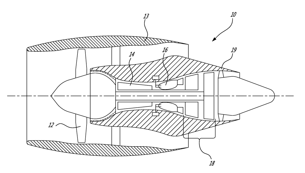
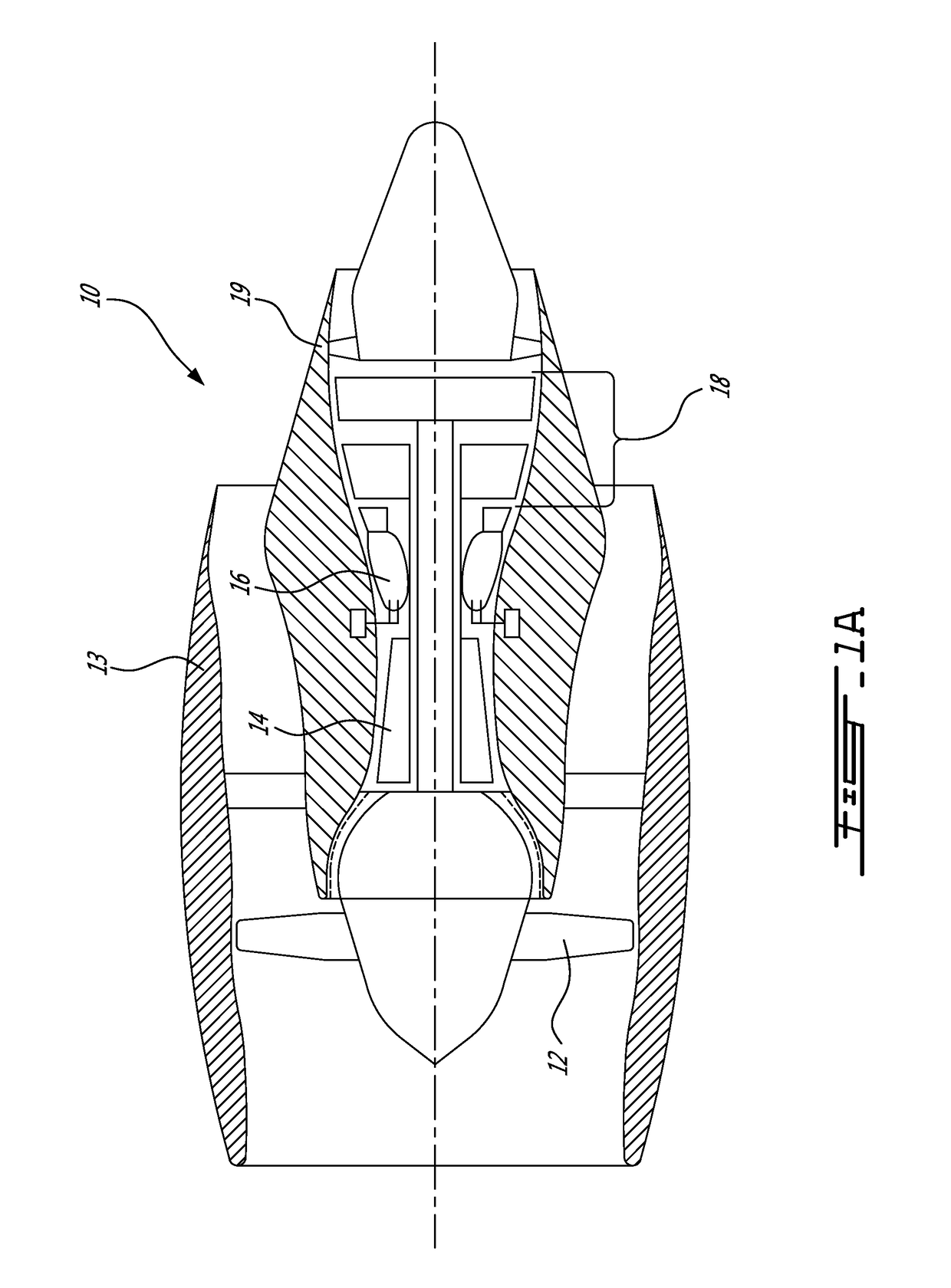
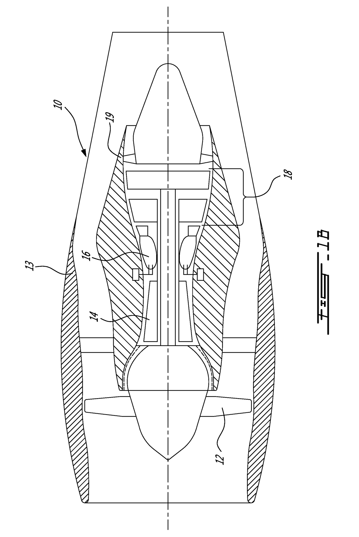
[0016]FIGS. 1A and 1B illustrate a turbofan gas turbine engine 10 of a type preferably provided for use in subsonic flight, generally comprising in serial flow communication a fan 12 in an outer case 13 through which ambient air is propelled, a multistage compressor 14 for pressurizing the air, a combustor 16 in which the compressed air is mixed with fuel and ignited for generating an annular stream of hot combustion gases, and a turbine section 18 in a turbine case 19 for extracting energy from the combustion gases. The gas turbine engine 10 of FIG. 1A is a short cowl engine, whereas the gas turbine engine 10 of FIG. 1B is a long cowl engine.

[0017]Referring to FIGS. 2A and 3A, a gas turbine engine case or nacelle is shown as having an outer skin 20, an inner skin 21, so as to define an inner cavity 22 therebetween. The gas turbine engine case is annular, whereby the inner cavity 22 is annular, as observed from FIGS. 2B and 3B. An annular opening 23 is circumscribed by trailing edge...


PUM


Abstract

A surface-increasing feature system for a gas turbine engine comprising deployable surface-increasing features such as chevrons each defined by panels connected to a deployment mechanism providing a translational actuation to deploy said deployable surface-increasing feature from a stowed configuration concealed fore of a trailing edge of a case of the gas turbine engine, to a deployed configuration extending beyond the trailing edge. Joints provide one or more degree of freedom for the first panel and the second panel relative to the deployment mechanism. A guide operatively contacts the deployable surface-increasing feature to rotatably displace the first panel and the second panel away from one another in the at least one degree of freedom in response to movement induced by the translational actuation from the stowed configuration to the deployed configuration. A footprint of the deployable surface-increasing feature concurrently defined by the first panel and the second panel is greater in the deployed configuration than in the stowed configuration

Description

TECHNICAL FIELD[0001]The application relates generally to gas turbine engines and, more particularly, to chevrons and like surface-increasing features.BACKGROUND OF THE ART[0002]The exhaust jet of a gas turbine engine remains a significant noise source, particularly at high power conditions. Chevrons located at the trailing edge of nozzles have emerged as an effective means of noise reduction in mid-to-high bypass ratio turbo-fan engines. The chevrons are the saw-tooth patterns on the trailing edges of jet engine nozzles. The chevron nozzles induce additional mixing mechanisms within the shear layer thereby promoting a rapid plume decay and resulting in noise reduction. This may however be accompanied by an increased drag which results in a deterioration of the performance of the gas turbine engine.SUMMARY[0003]In one aspect, there is provided a surface-increasing feature system for a gas turbine engine comprising: at least one deployable surface-increasing feature defined at least ...

Claims


Application Information

Patent Timeline
IPC IPC(8): F02K1/46F02K1/34F01D25/24F02K1/54F02K1/08
CPCF02K1/46F02K1/54F02K1/08F05D2220/32B64D33/06F05D2260/962F01D25/24
Inventor JOSHI, NINADMESLIOUI, SID-ALI
Owner PRATT & WHITNEY CANADA CORP
Learn More