
Articulated floor scrubber

Inactive Publication Date: 2007-07-12
TREK CLEANING MACHINES
View PDF8 Cites 5 Cited by
  • Summary
  • Abstract
  • Description
  • Claims
  • Application Information

AI Technical Summary

Benefits of technology

[0011] In another embodiment of the scrubber, the second pair of wheels, the pair associated with the rear scrubber portion, employ pneumatic tires that are of a greater width than the casters used in prior art walk behind scrubbers. The use of wider pneumatic tires has a number of advantages relative to the prior art casters. Namely, due to the greater footprint of the tires relative to casters, less pressure is transmitted to the floor by the tires, thereby reducing the possibility of damaging the floor. Additionally, the tires are noticeably less noisy than casters. In another embodiment, all four wheels employ pneumatic tires.
[0012] In a further embodiment, the first and second pairs of tires are located further from one another than prior art walk-behind scrubbers of comparable overall length. As a consequence, the scrubber is more stable than prior art walk-behind scrubbers.
[0013] A further embodiment of the scrubber allows an operator to stand on a platform associated with the rear scrubber portion. Yet another embodiment allows the operator to assume a sitting position adjacent the rear scrubber portion.

Problems solved by technology

Many such scrubbers are not self-propelled or are self-propelled but do not have differential speed control.
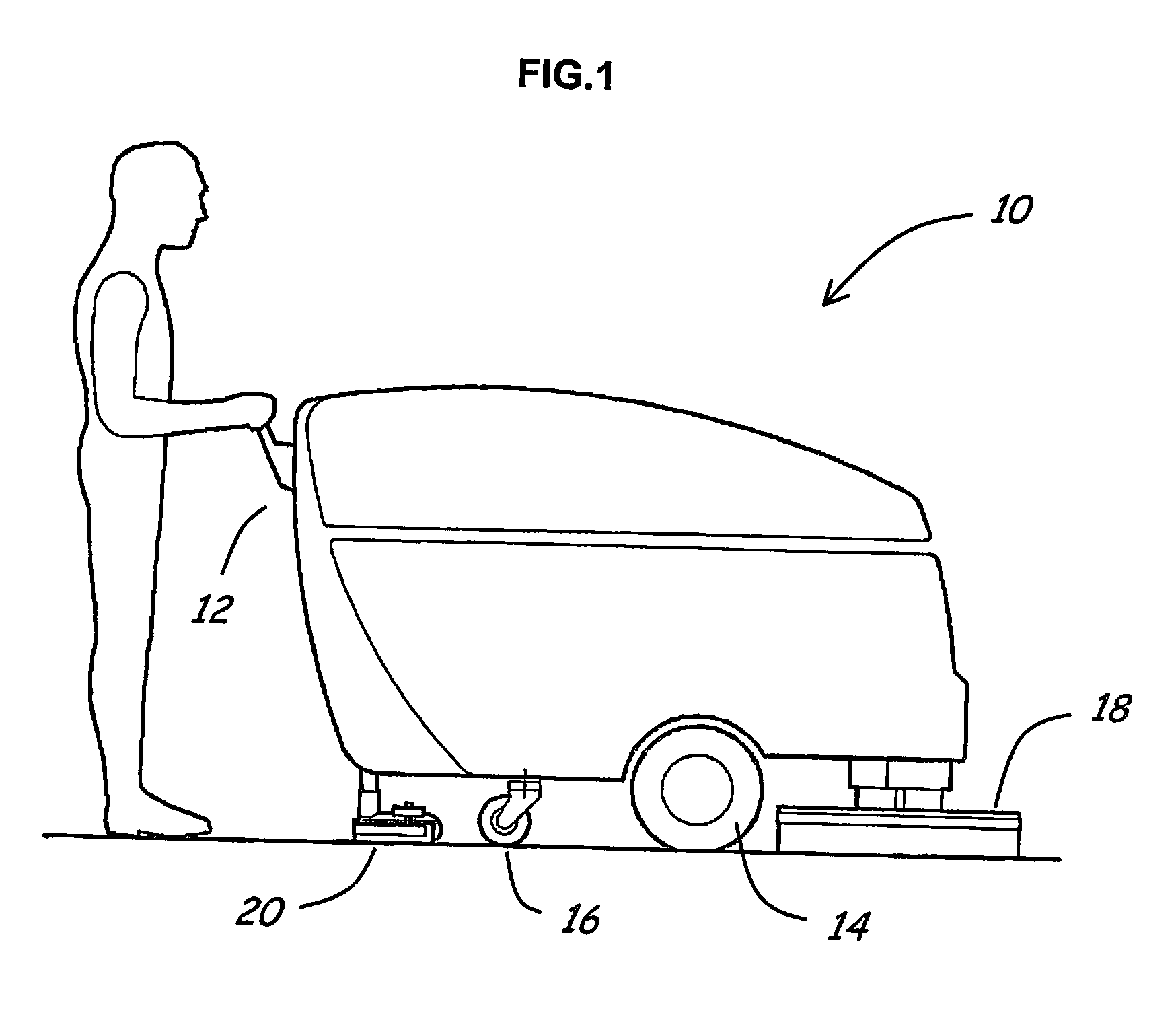
However, as the weight of the scrubber increases, fine steering control becomes more difficult, particularly when attempting to steer in tight quarters and / or when steering is accomplished by physically pushing the rear of the scrubber to the right or left.
Further, in some situations, such scrubbers are so difficult to maneuver that the floor is more efficiently cleaned by hand mopping.
As a consequence, prior art walk-behind floor scrubbers can adversely affect productivity, especially if operated over long periods of time and / or the floor being cleaned requires substantial maneuvering of the scrubber.

Method used


Image

  • Articulated floor scrubber
  • Articulated floor scrubber
  • Articulated floor scrubber

Examples


Embodiment Construction

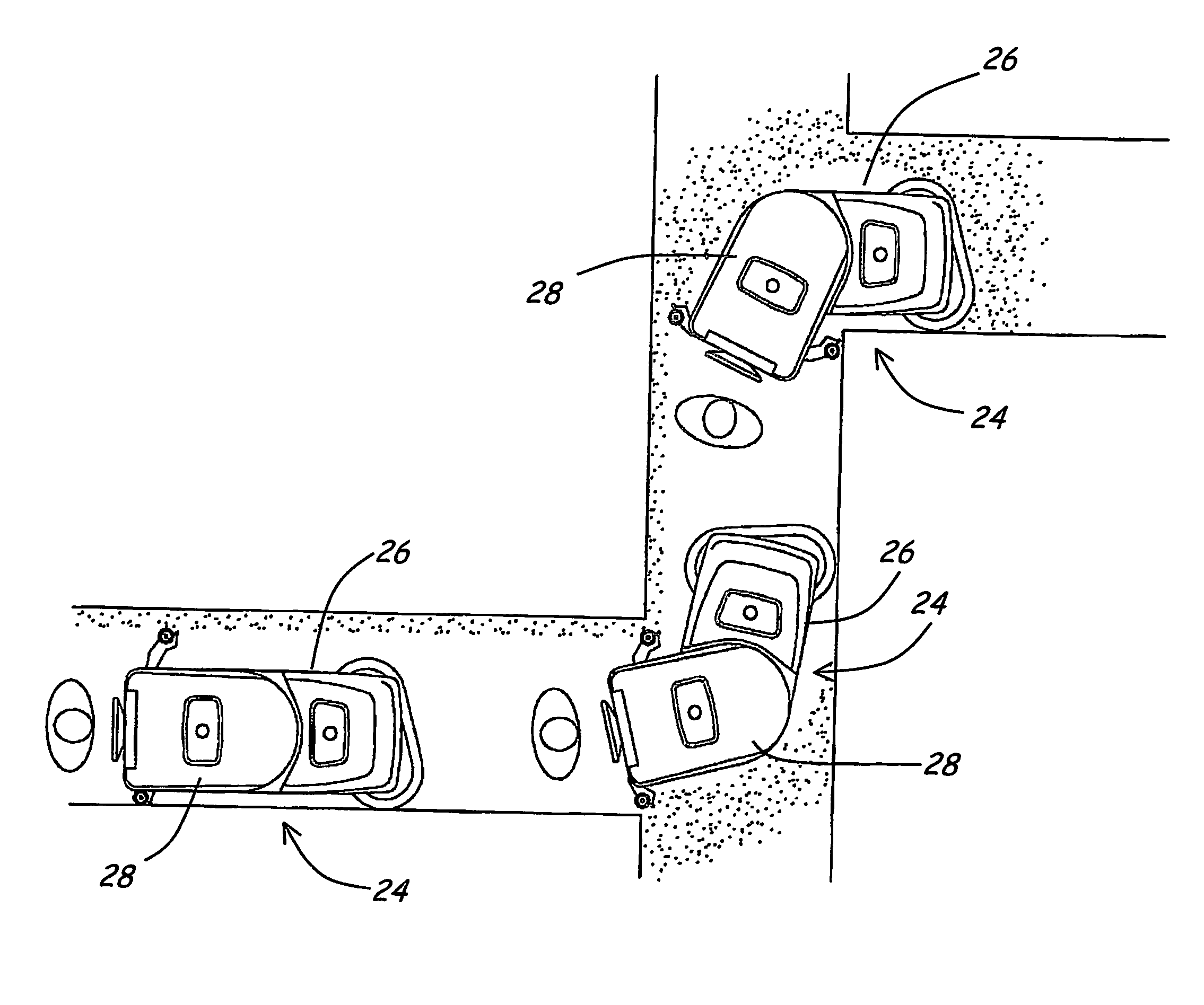
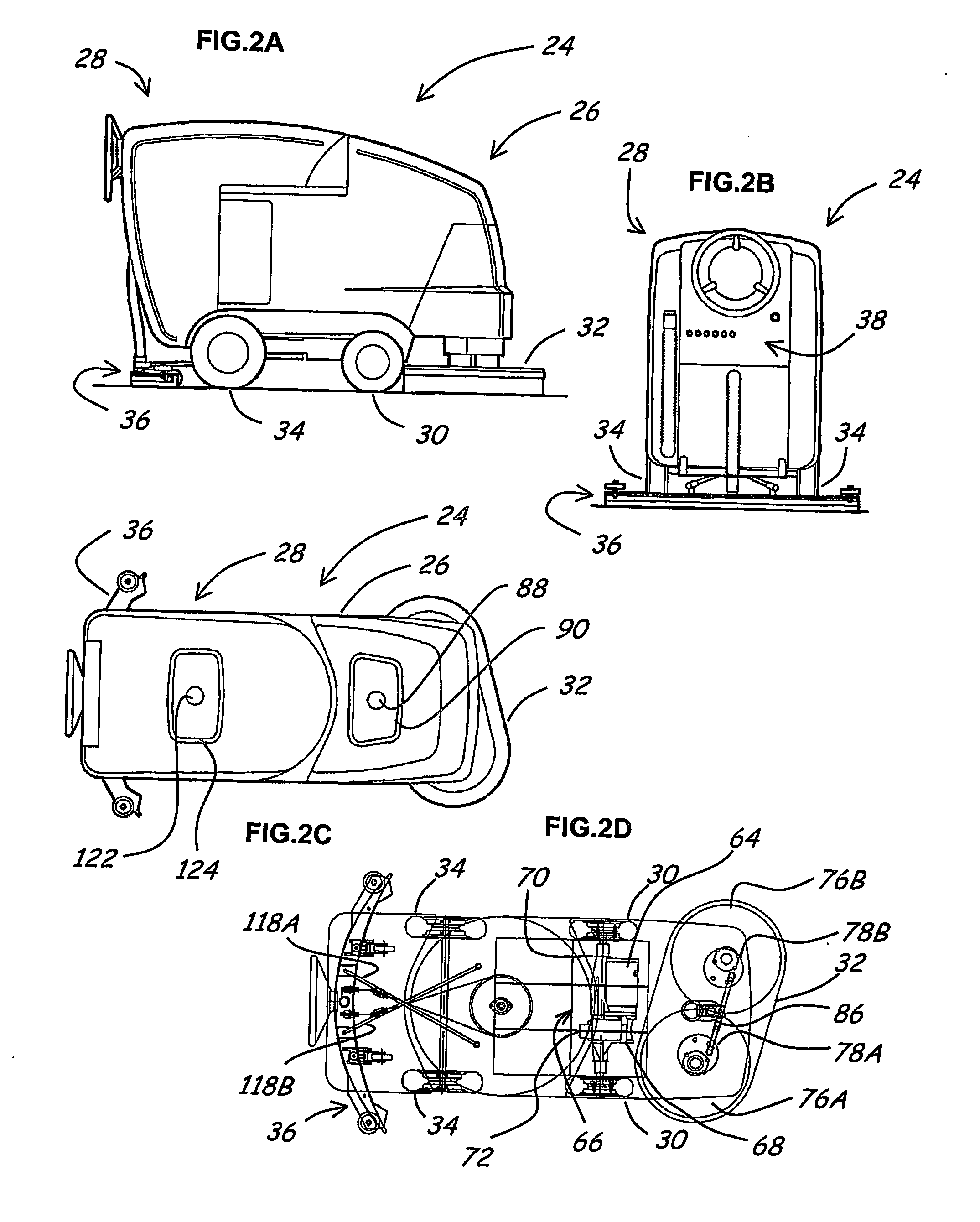
[0030] With reference to FIGS. 2A-2C, an embodiment of a rear-operated articulated scrubber 24 is described. The scrubber 24 comprises a front portion 26 and a rear portion 28 that is pivotally attached to the front portion 26. Associated with the front portion 26 is a pair of non-steerable front wheels 30 and a scrub head 32. Associated with the rear portion 28 is a pair of non-steerable rear wheels 34 and a vacuum squeegee assembly 36. Also associated with the rear portion 28 is an operator interface 38 that allows an operator to steer the scrubber 24 and otherwise control the scrubber 24.

[0031] With reference to FIG. 3, the scrubber 24 further comprises a solution tank 40 for holding a cleaning solution (e.g., water, soap and water etc.) and a recovery tank 42 for holding whatever cleaning solution and entrained debris that the vacuum squeegee 36 picks up from a floor. The solution tank 40 is associated with the front portion 26 of the scrubber 24. The recovery tank 42 is associ...


PUM


Abstract

A rear-operated, articulated floor scrubber (24) is disclosed. In one embodiment, the scrubber (24) comprises a front portion (28), a rear portion (28) that is pivotally connected to the front portion (26), and an operator interface (38) associated with the rear portion (28). The scrubber (24) further comprises a solution tank (40) for hold cleaning solution and a recovery tank (42) for holding cleaning solution and entrained debris that is picked up from the floor after the floor has been scrubbed. In one embodiment, a portion (26, 28) of one of the tanks (40, 42) overlies a portion (26, 28) of the other tank (40, 42).

Description

FIELD OF THE INVENTION [0001] The invention relates to floor scrubbing machines that apply a cleaning liquid to a floor to be cleaned, scrub the floor to which the cleaning liquid has been applied, and remove liquid and entrained debris from the floor after the floor has been scrubbed. More specifically, the present invention relates to an articulated floor scrubber that comprises a front portion and a rear portion that are pivotally connected to one another. BACKGROUND OF THE INVENTION [0002] U.S. Pat. No. 5,742,975 discloses an articulated floor scrubber that has a wheel-supported front portion that is pivotally connected to a wheel-supported rear portion. Associated with the front portion are an operator's seat, a steering wheel, a forward / reverse foot-pedal, a brake foot-pedal and a control panel. A steering linkage that utilizes a cable and pulley system operates such that counterclockwise (CCW) rotation of the steering wheel produces a left-turn of the scrubber and clockwise (...

Claims


Application Information

Patent Timeline
IPC IPC(8): A47L11/30A47L11/40B62D51/00B62D51/04
CPCA47L11/30A47L11/302A47L11/4061B62D53/045B62D51/02B62D51/04B62D53/02B62D51/008
Inventor O'HARA, ROBERT J.
Owner TREK CLEANING MACHINES
Learn More