Weight bar slide assembly

Active Publication Date: 2009-06-23
RECREATION SUPPLY
View PDF43 Cites 84 Cited by
  • Summary
  • Abstract
  • Description
  • Claims
  • Application Information

AI Technical Summary

Benefits of technology

[0004]Many innovations in the field of weightlifting equipment have attempted to balance the needs of weightlifters by attempting to provide the freedom of motion found in the use of free weights and the safety found in the use of weightlifting machines. One such device that embodies the balance between freedom of motion and the safety concerns is know as a power rack, power cage, or “Smith Machine.” Such a device allows a weightlifter to use free weights without the need for a spotter. This is accomplished through the connection of a pair of side frames to a back frame. Vertical guide bars carry a weight bar slide assembly which can slide along the length of the vertical guide bar. A weight bar runs laterally and is carried by the weight bar slide assembly. Free weights can be added to the weight bar. While standing in the device a weightlifter can lift the weigh bar up and down within the device. To eliminate the need for a spotter, the device provides a method of racking the weight bar during any point of the exercise motion.
[0005]Further innovations increased the freedom of motion available to the weightlifter. Devices such as the “Max Rack” and similar devices have added a horizontal guide bar to the vertical guide bars found in power cages or “Smith Machines” allowing the weightlifter to move the weight bar both horizontally and vertically within the device.
[0006]While the safety feature described above is comparable to the safety features found on weightlifting machines, the weight bar remains parallel to the floor. An exemplary embodiment of the present invention provides a weigh

Problems solved by technology

The need for a spotter has limited the use of free weights to situations w

Method used


Image

  • Weight bar slide assembly
  • Weight bar slide assembly
  • Weight bar slide assembly

Examples


Embodiment Construction

)

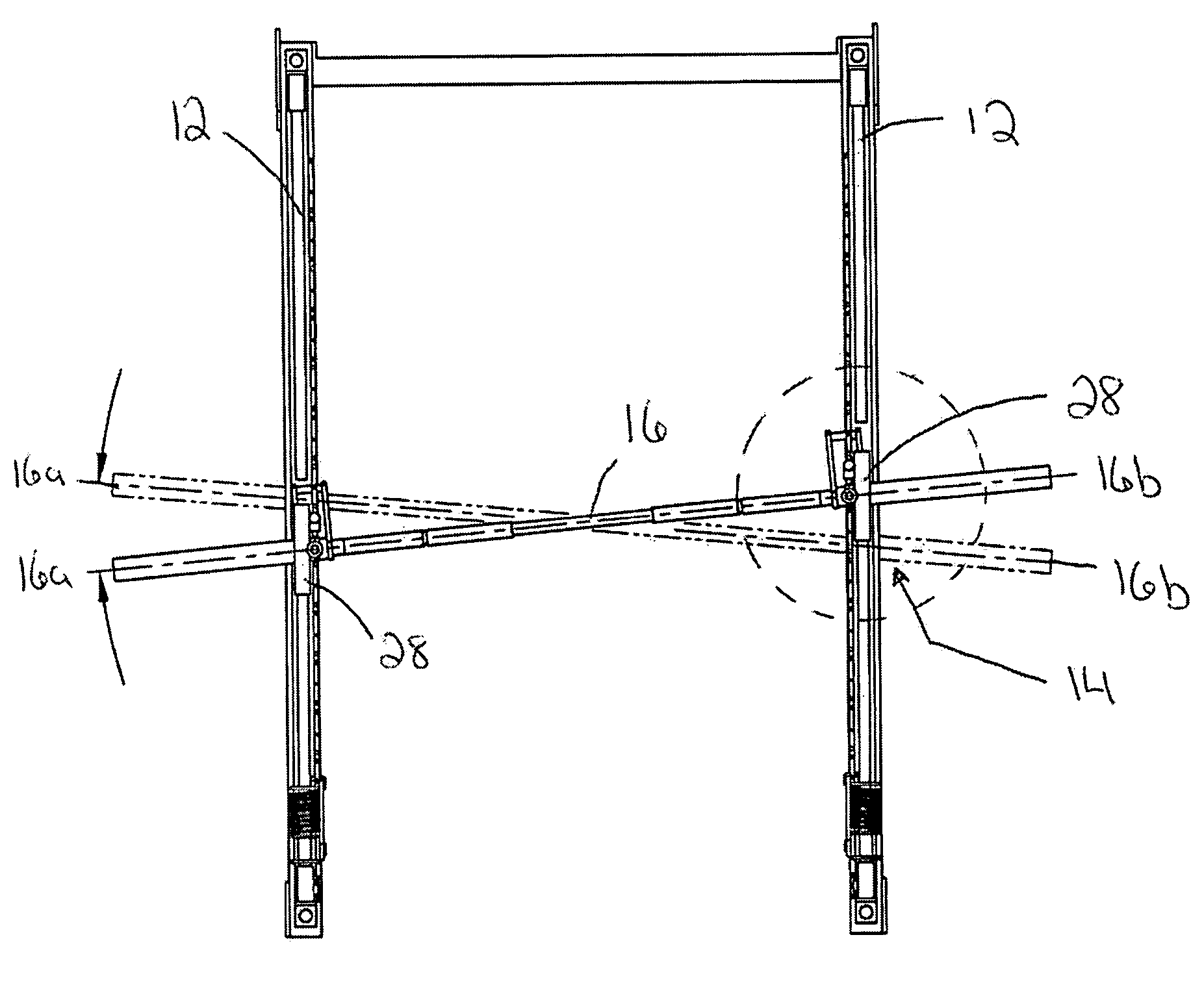
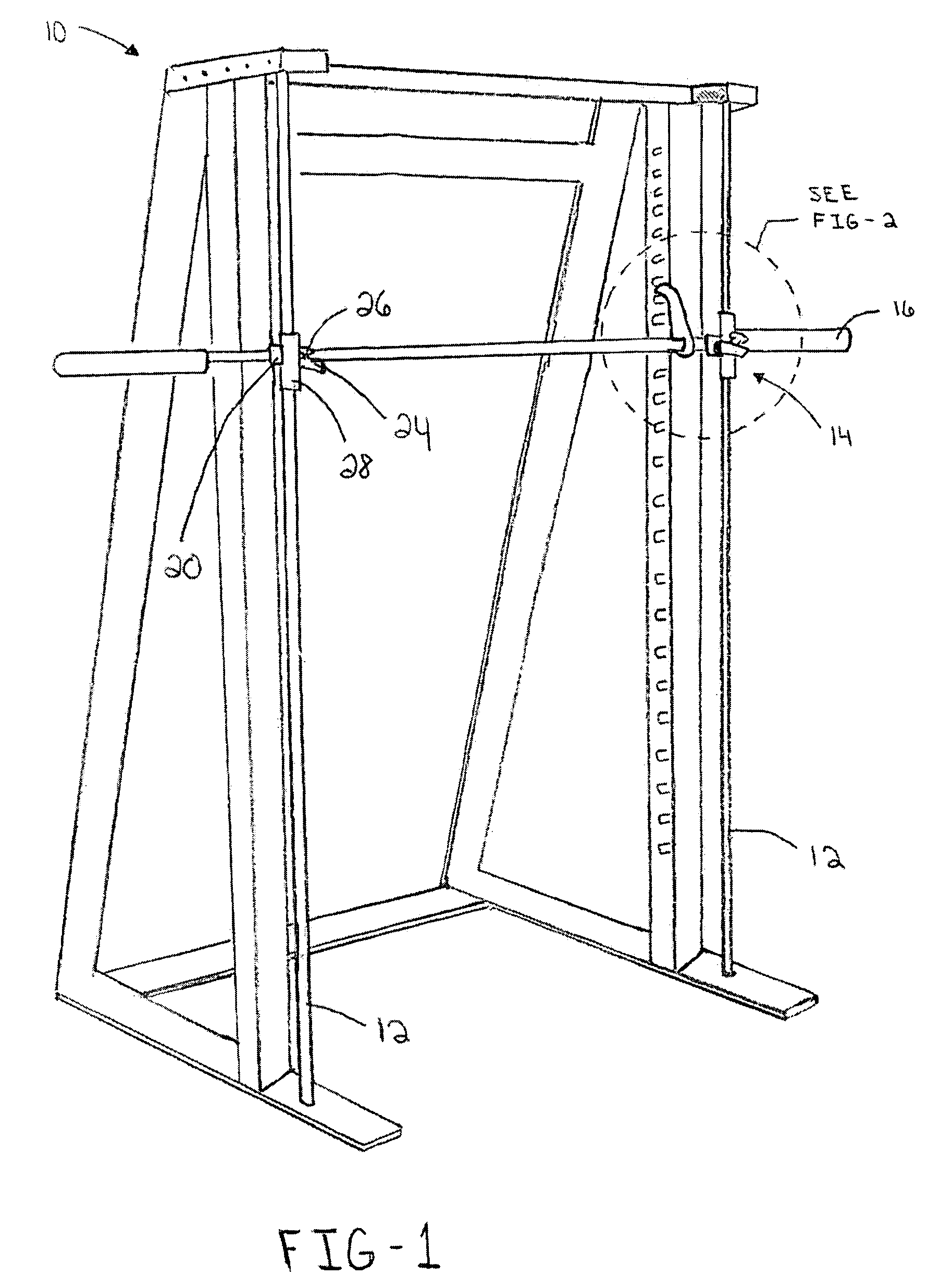
[0024]Referring now to the example of FIG. 1, a weight lifting power cage 10 is shown having a pair of vertical guide bars 12. Weight bar slide assemblies 14 are movably attached to the vertical guide bars 12. A weight bar 16 is retained by the weight bar slide assembly 14. The weight lifting power cage 10 is an example of a type of weight lifting device that may benefit from the present invention. The weight bar slide assemblies 14 of the present invention can be used with weightlifting equipment having vertical guide bars, including, but not limited to “Smith Machines”, power lifting cages, or power racks.

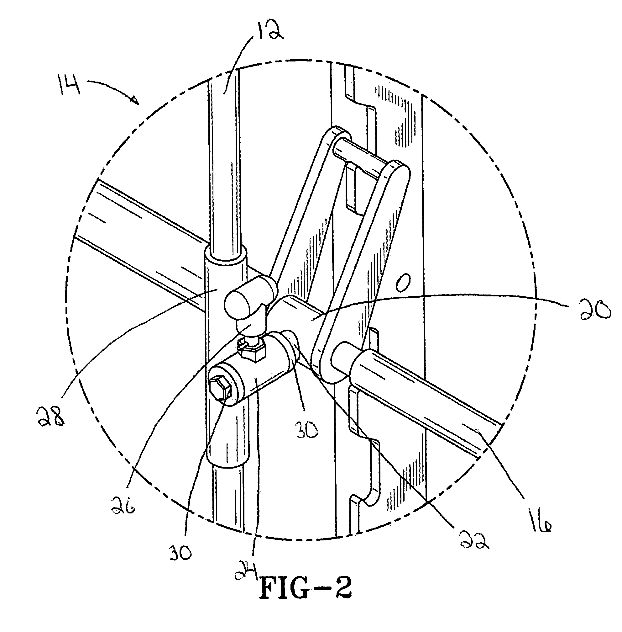
[0025]Referring to FIG. 2, the weight bar slide assembly 14 has a weight bar sleeve 20. The weight bar sleeve 20 having a passage disposed therein for rotatably receiving a weight bar 16. A rod 22 is fixed to the weight bar sleeve 20 and extends outwardly therefrom. A rod sleeve 24 rotatably receives the rod 22 and allows rotation of the rod within the rod sleeve in both directi...


PUM


Abstract

A weight bar slide assembly, for use with weightlifting equipment having vertical guide bars that provide for an accurate simulation of the free weight lifting motion. The weight bar slide assembly has a weight bar sleeve to rotatably receive a weight bar. A rod is attached to the weight bar sleeve and extends outwardly therefrom. A rod sleeve rotatably receives the rod. The rod may rotate along its longitudinal axis inside the rod sleeve. The rod sleeve is attached to a vertical guide. The vertical guide is movably mounted to a vertical guide bar. The longitudinal axis rotation of the rod within the rod sleeve allows for the freedom of motion found in the free weight lifting motion. The weight bar slide assemblies attached to opposing ends of the weight bar may move linearly along the vertical guide bar independently of each other.

Description

BACKGROUND AND SUMMARY OF THE INVENTION[0001]The present invention relates generally to exercise equipment and, more particularly to a weight lifting device having a weight bar slide assembly.[0002]Many weightlifters perform a variety of exercises to build and develop muscle. These exercises can be performed through the use of free weights or the use of weightlifting machines. While both free weights and weightlifting machines provide a means to develop and build muscle, many weightlifters prefer the natural motion afforded by the use of free weights. The ability to move naturally allows the weightlifter a greater degree of variety in their exercise routine and the ability to isolate specific muscles. Although a variety of weightlifting machines have been developed to imitate the freedom of motion found in the use of free weights, the weightlifter's movements must still conform to the limitations of the weightlifting machine.[0003]Even though the use of free weights in weight traini...

Claims


Application Information

Patent Timeline
IPC IPC(8): A63B21/062
CPCA63B21/078A63B2021/0614A63B2021/0783A63B21/0626A63B21/0783
Inventor LUNDQUIST, RANDAL L.GORE, ALAN W.
Owner RECREATION SUPPLY
Why Eureka
Try Eureka