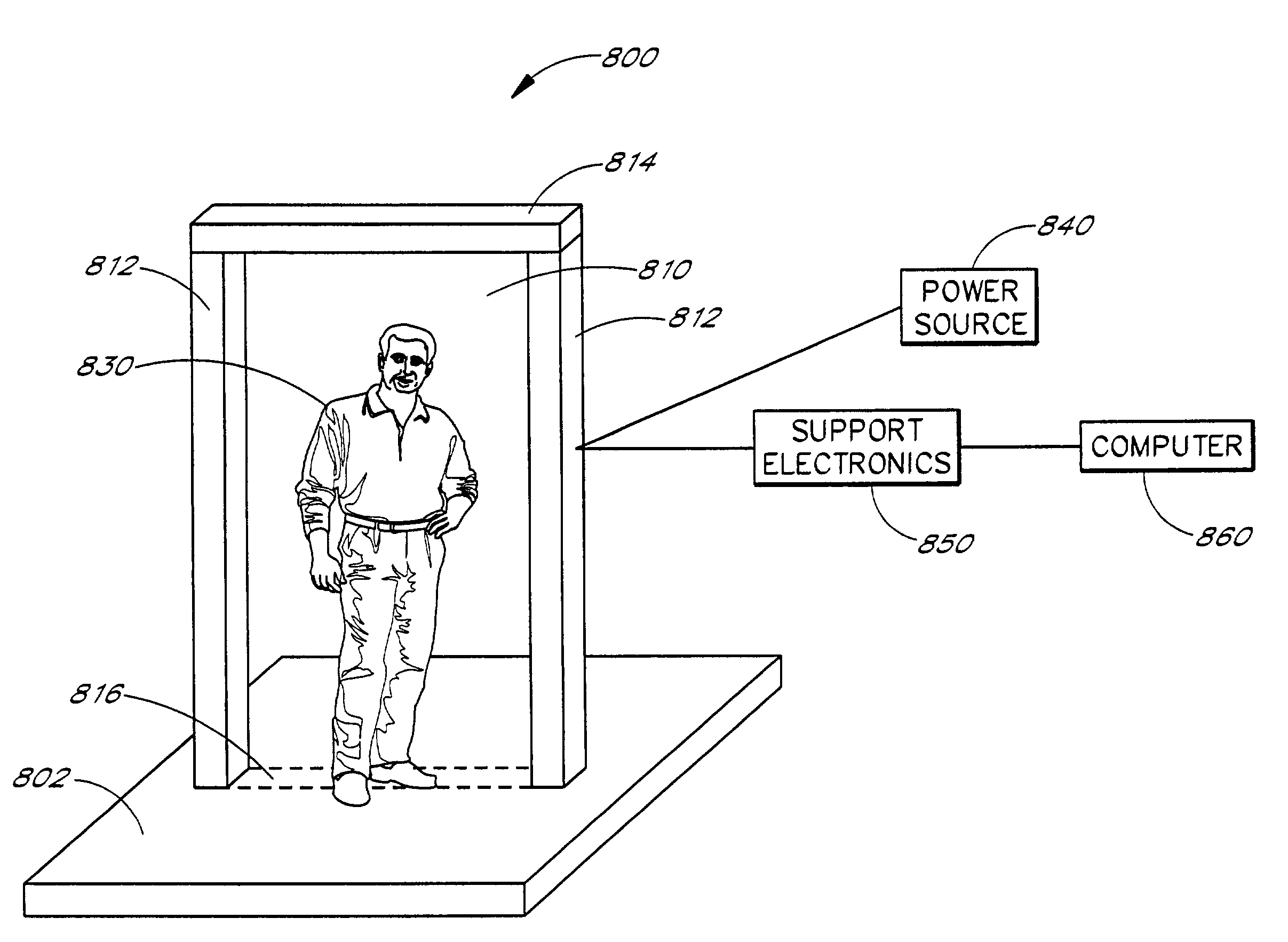
Security screening and inspection based on broadband electromagnetic holographic imaging
a technology of electromagnetic holographic imaging and security screening, applied in the field of three-dimensional holographic imaging, can solve the problems of limited success in developing a method for quickly interpreting geophysical em data over two-dimensional geoelectrical structures, and not pointed to a practical useful method for accomplishing broadband em imaging of three-dimensional objects in non-transparent media
- Summary
- Abstract
- Description
- Claims
- Application Information
AI Technical Summary
Benefits of technology
Problems solved by technology
Method used
Image
Examples
example 1
[0035]The following explanation of the principles of broad band EM holographic imaging reconstruction is offered to assist those skilled in the art to practice the invention. It is not intended thereby to limit the scope of the invention to any particular theory of operation or to any field of application.
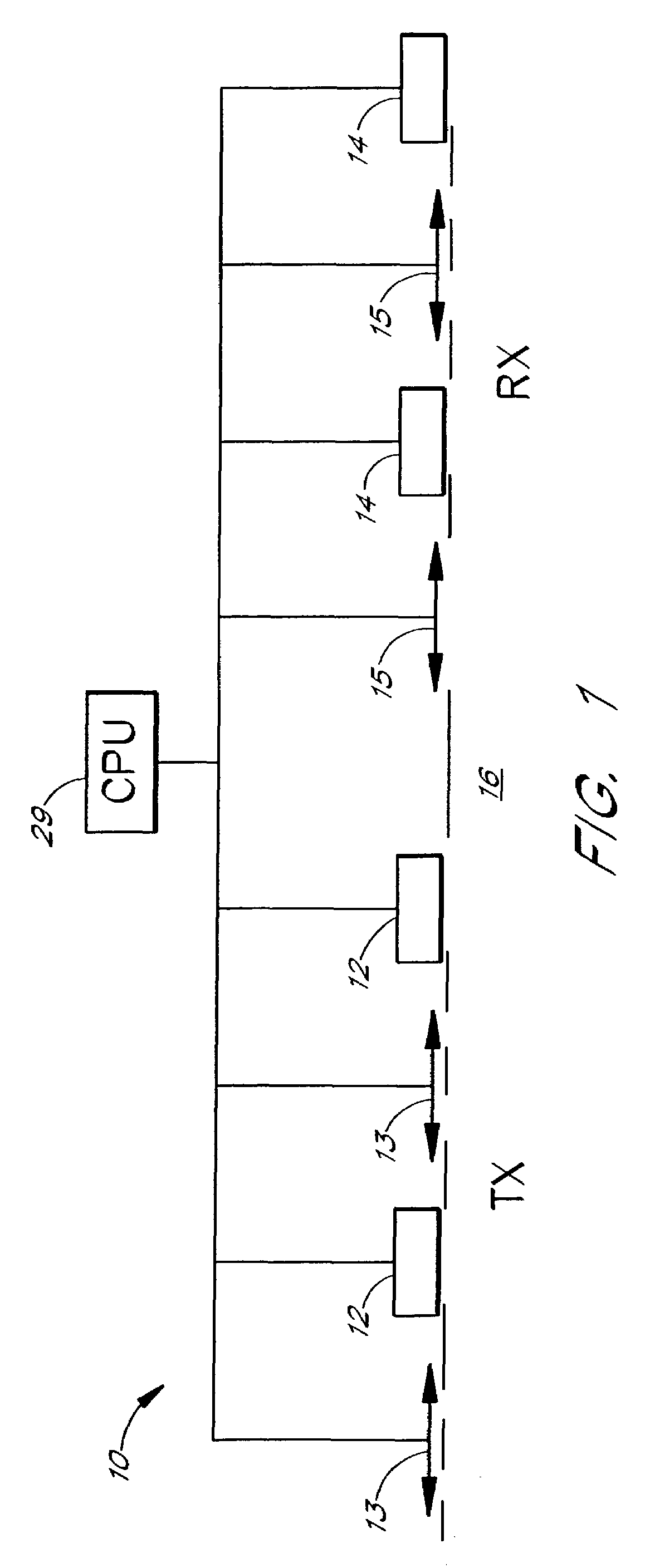
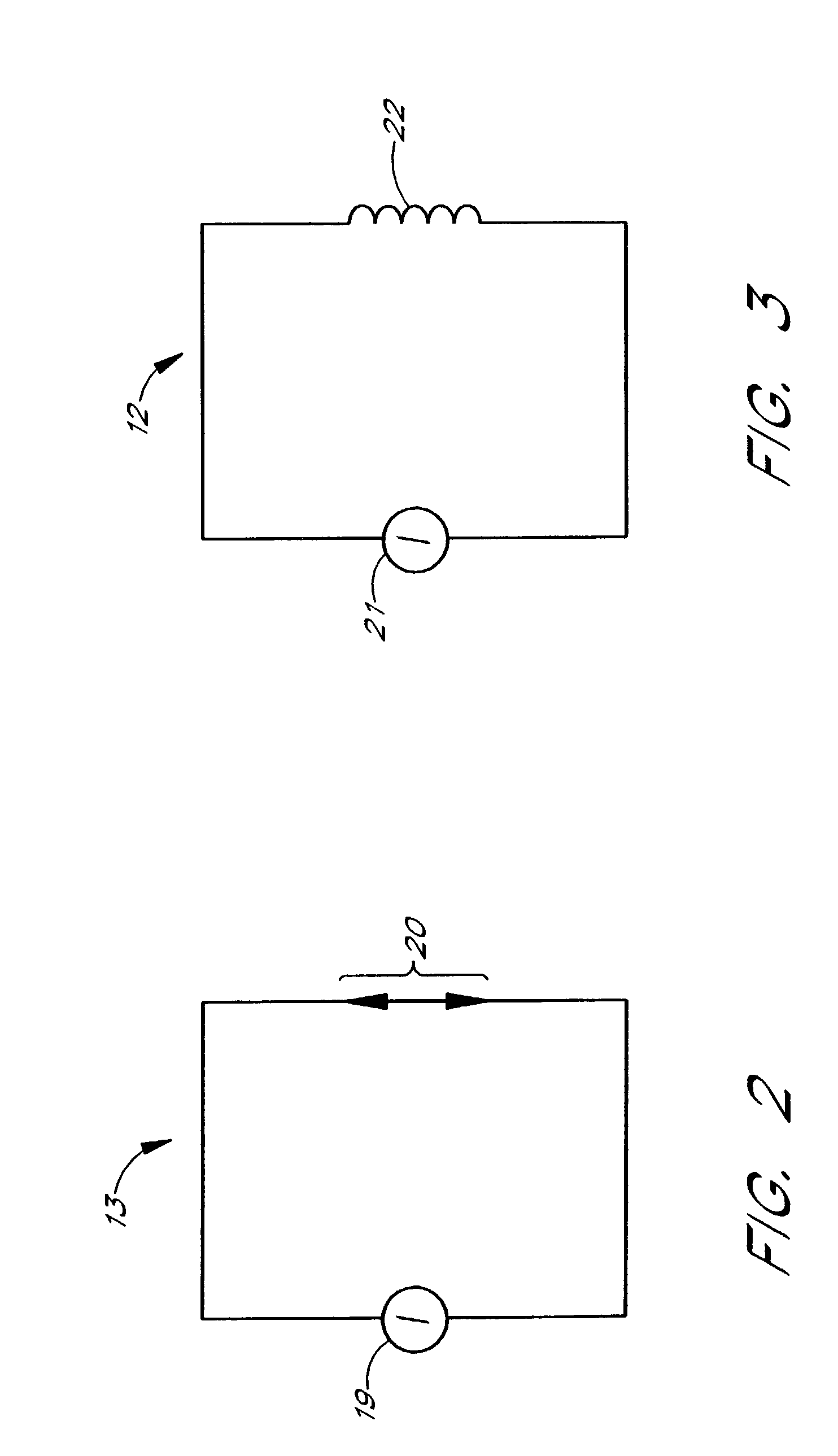
[0036]A three dimensional inhomogeneous medium, with a known background complex conductivity, {tilde over (σ)}b, contains a local inhomogeneous object D with an arbitrarily varying complex conductivity {tilde over (σ)}={tilde over (σ)}b+{tilde over (σ)}a. The location of D and its anomalous conductivity {tilde over (σ)}a, are unknown. The examined medium is considered to be non-magnetic, and hence μ=μ0=4π×10−7H / m, where μ is the magnetic permeability and μ0 is the free-space magnetic permeability. The model is excited by an EM field generated by a given system of sources (transmitters TX) with an electric current density je. This field is time harmonic as e−iωt and is observed by t...
example 2
[0046]The image generating method solves the minimum energy flow problem for the residual field {EΔ,HΔ} computed as the difference between the observed field {Eobs,Hobs} and numerically calculated (predicted) field {Epr,Hpr} for a constructed image.
[0047]The energy flow of the residual electromagnetic field can be calculated using the complex Poynting vector P, introduced by the formula:
[0048]P=12EΔ×HΔ*,(3)
which is known to be a non-negative function.
[0049]The measure Φ of the difference between the observed and predicted fields can be introduced as the energy flow of the residual field through the surfaces of observations, integrated over the frequency ω:
[0050]The theoretical predicted fields Epr (r,ω), Hpr (r,ω) depend on the sum of the background {tilde over (σ)}b(r) and anomalous conductivity distribution {tilde over (σ)}a(r) in the examined
[0051]Φ=Re∫Ω∫∫SP·nⅆsⅆω=12Re∫Ω∫∫S[EΔ(r,ω)×HΔ*(r,ω)]·nⅆsⅆω(4)
medium, and, therefore, the residual field energy flow φ is a f...
example 3
[0070]It is possible to improve the resolution of imaging by repeating the steps of the previous examples iteratively. This procedure solves the inverse problem for determination of the material properties and location of the target.
[0071]The general iterative process can be described by the formula:
{tilde over (σ)}a(n+1)(r)={tilde over (σ)}a(n)(r)+knAn(r)−iωBn(r) (25)
where n=1, 2, 3, . . . , N; k1=k; A1(r)=A(r), B1(r)=B(r); and {tilde over (σ)}a(1)(r)=σa(r)−iωkB(r)=kA(r)−ωkB(r).
[0072]The cross power spectra on the n-th iteration An(r) an dBn(r) can be calculated by formulae, analogous to (1) and (11) in the frequency domain:
An(r)=Re∫ΩEnb(r,ω)·Ena(r,ω)dω,
Bn(r)=Re∫Ω(−iω)Enb(r,ω)·Enb(r,ω)dω, (26)
where Enb(r,ω) is the corrected background field calculated by forward modeling for the geoelectrical model with the corrected background conductivity distribution {tilde over (σ)}b(n)={tilde over (σ)}a(n)+{tilde over (σ)}a(n), and En8(r,ω), is the corrected backscattering field of the corr...
PUM
| Property | Measurement | Unit |
|---|---|---|
| diameter | aaaaa | aaaaa |
| diameter | aaaaa | aaaaa |
| frequency | aaaaa | aaaaa |
Abstract
Description
Claims
Application Information
 - R&D
- Intellectual Property
- Life Sciences
- Materials
- Tech Scout
- Unparalleled Data Quality
- Higher Quality Content
- 60% Fewer Hallucinations
Browse by: Latest US Patents, China's latest patents, Technical Efficacy Thesaurus, Application Domain, Technology Topic, Popular Technical Reports.
© 2025 PatSnap. All rights reserved.Legal|Privacy policy|Modern Slavery Act Transparency Statement|Sitemap|About US| Contact US: help@patsnap.com


