Method and apparatus for tracking servo control of an optical disc playback apparatus

a technology of optical discs and servos, applied in the direction of digital signal error detection/correction, instruments, recording signal processing, etc., can solve the problems of large amplitude undesirable changes, and large turbulence of te signals, so as to improve vibration resistance during playback

Inactive Publication Date: 2009-06-23
ALPINE ELECTRONICS INC
View PDF8 Cites 2 Cited by
  • Summary
  • Abstract
  • Description
  • Claims
  • Application Information

AI Technical Summary

Benefits of technology

[0013]In order to overcome the problems of the related art, it is an object of the present invention to provide an optical disc playback apparatus in which a defective optical disc can be played back in a vibrating environment.
[0014]It is another object of the present invention to provide an optical disc playback apparatus in which servo is less susceptible to vibration.
[0019]According to a preferred embodiment of an optical disc playback apparatus, when a defect is detected on an optical disc, a correction signal indicating an oscillation component of an optical pickup is added to a hold signal applied to a driving control circuit to control driving of the optical pickup. Thus, even if a defective optical disc is played back in a vibration environment, high-response servo control of the optical pickup can be achieved for appropriate playback. Therefore, the vibration resistance during playback can be improved compared to an optical disc playback apparatus of the prior art.

Problems solved by technology

When a defect of the optical disc is detected, a TE signal (d) suffers large amplitude turbulence, and becomes undesirable.
However, an optical disc playback apparatus of the related art has the following problems.
When the optical disc apparatus is in an environment susceptible to shock or vibration, e.g., in a vehicle, an external force caused by shock or vibration affects an optical pickup.
In passing through defects, the farther from the target track the lens position is, the larger turbulence the TE signal suffers at the on-track time after the level holding for the defects.
Therefore, in playing back a defective optical disc, a problem occurs in that servo is susceptible to vibration.

Method used


Image

  • Method and apparatus for tracking servo control of an optical disc playback apparatus
  • Method and apparatus for tracking servo control of an optical disc playback apparatus
  • Method and apparatus for tracking servo control of an optical disc playback apparatus

Examples


first embodiment

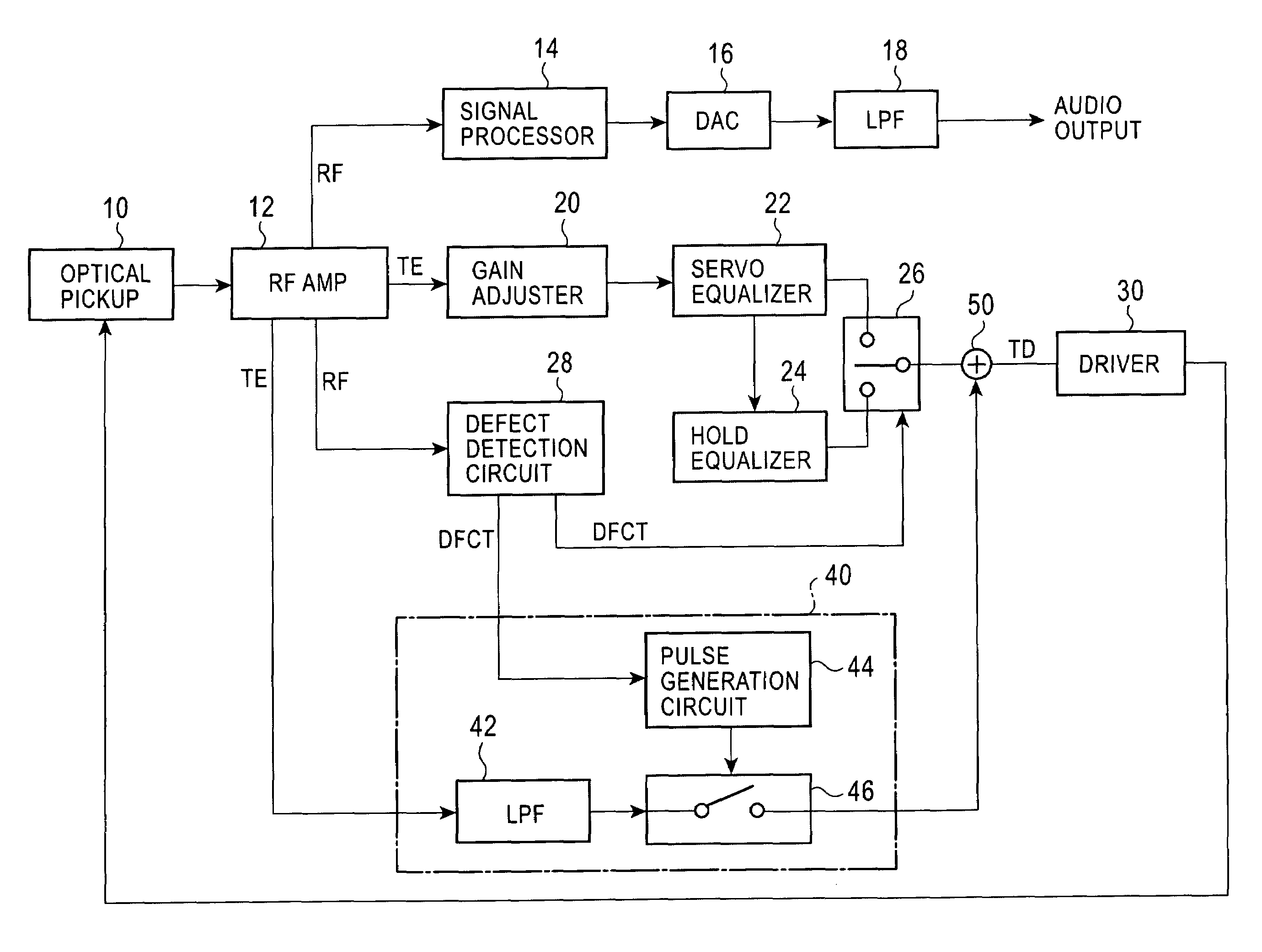
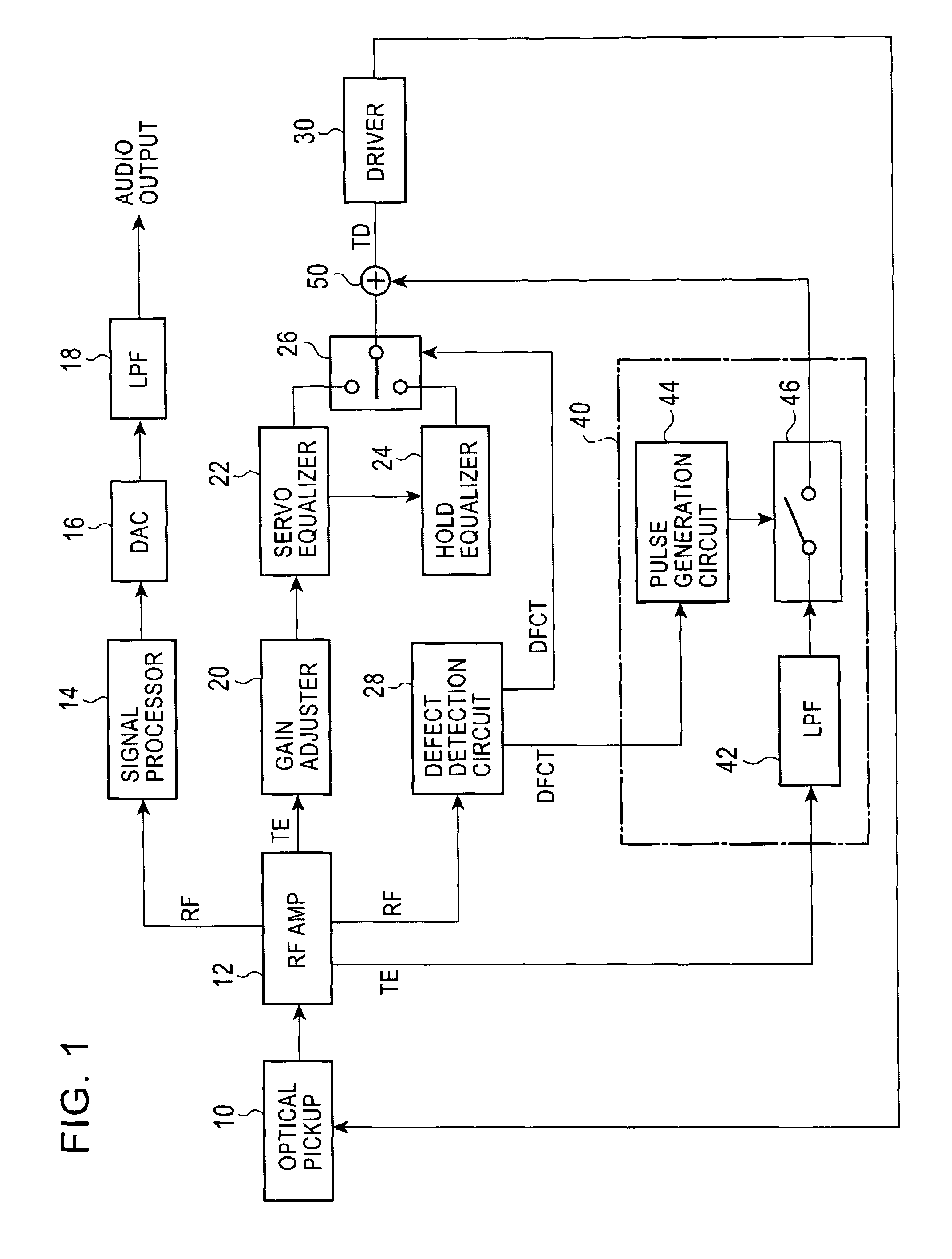
[0032]FIG. 1 is a block diagram of an optical disc playback apparatus according to a The same parts as those of the optical disc playback apparatus shown in FIG. 7 are given the same reference numerals. As shown in FIG. 1, the optical disc playback apparatus includes an optical pickup 10 and an RF amplifier 12. The optical pickup 10 irradiates a recording surface of an optical disc with laser light, and converts the reflected light into an electrical signal. The RF amplifier 12 receives the electrical signal from the optical pickup 10, and generates an RF playback signal, a tracking error signal (TE signal), etc. The signal output from the RF amplifier 12 is audibly output via a signal processor 14, a digital-to-analog converter (DAC) 16, and a low-pass filter (LPF) 18, and is converted into an audible sound by a speaker.

[0033]In order to perform tracking servo on the optical pickup 10, the TE signal from the RF amplifier 12 is supplied as a tracking driving signal (TD signal) to a...

second embodiment

[0051]In the second embodiment, the corrector 40 further includes a pulse width control circuit 48 for varying the width of the pulse signal output from the pulse generation circuit 44. The pulse width control circuit 48 includes an AND circuit that carries out the logical AND between a pulse signal Pc from the pulse generation circuit 44 and a DFCT signal, and controls the pulse width corresponding to the size of a defect on an optical disc.

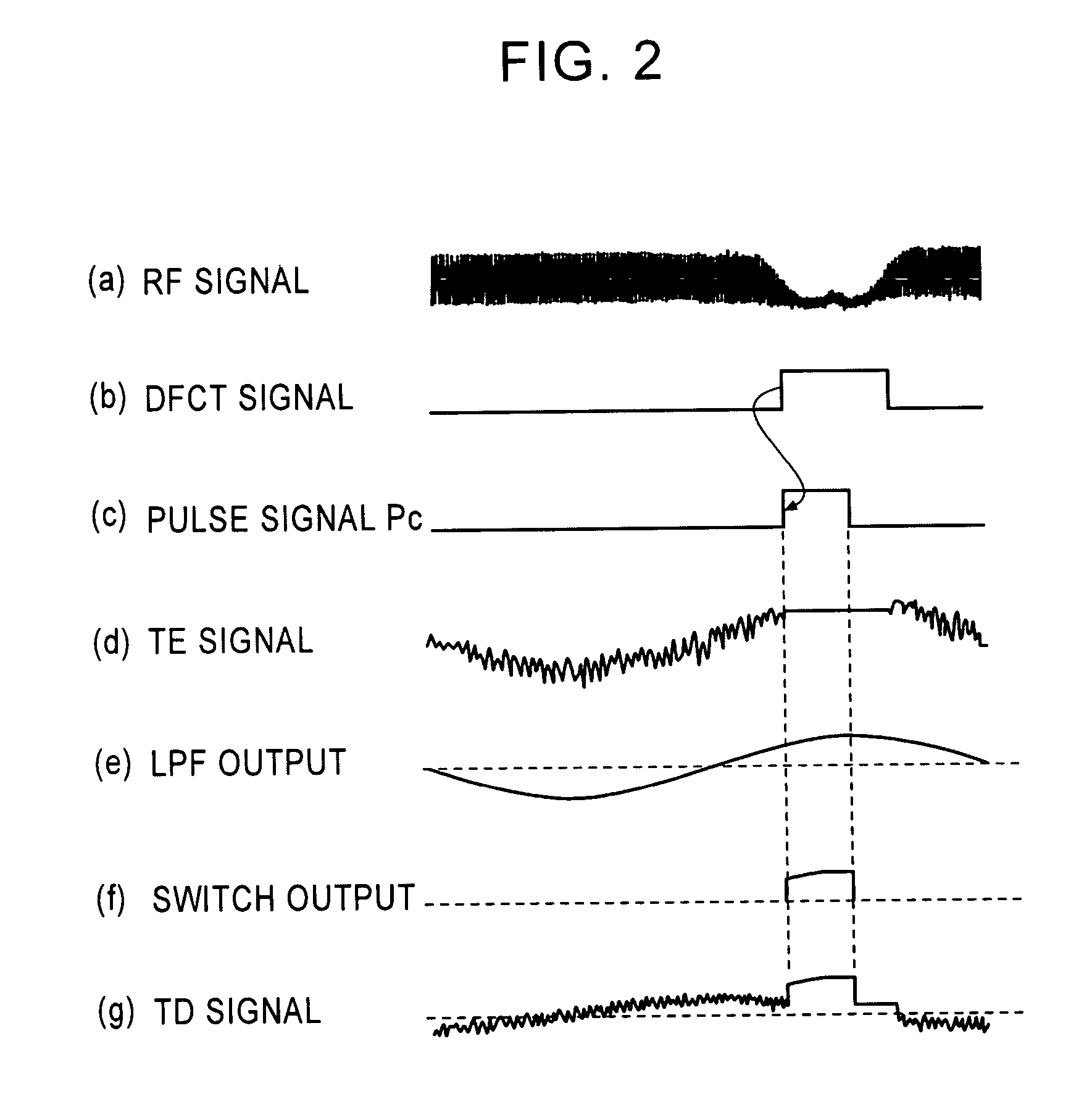
[0052]FIGS. 6A and 6B are waveforms showing that a disc having a large scratch width and a disc having a small scratch width are played back by the optical disc playback apparatus of the second embodiment, respectively.

[0053]The larger the scratch width, the longer the period of time during which the RF signal falls, as indicated by (a). Thus, as indicated by (b), the pulse width of the DFCT signal becomes longer. The pulse generation circuit 44 outputs a pulse signal Pc having a constant pulse width, as indicated by (c). The pulse width control...


PUM

PropertyMeasurementUnit
frequencyaaaaaaaaaa
frequencyaaaaaaaaaa
defectaaaaaaaaaa

Abstract

An optical disc playback apparatus includes an optical pickup, an RF amplifier that generates a tracking error (TE) signal based on an electrical signal from the optical pickup, a defect detector that detects a defect on the optical disc and that outputs a DFCT signal indicating the detected defect, a switch that outputs a hold signal when a defect is detected based on the DFCT signal, a driver that controls the optical pickup based on the output signal of the switch, a corrector that extracts an oscillation component of the optical pickup from the TE signal in response to the DFCT signal when a defect is detected and that outputs a correction signal indicating the oscillation component, and an adder that adds the correction signal from the corrector to the hold signal.

Description

BACKGROUND OF THE INVENTION[0001]1. Field of the Invention[0002]The present invention relates to an optical disc playback apparatus for optically reading and / or playing back data recorded in a disc-shaped recording medium (hereinafter referred to as an optical disc), such as a CD (Compact Disc) or a DVD (Digital Versatile Disc). More specifically, the present invention relates to tracking servo control of an optical disc playback apparatus.[0003]2. Description of the Related Art[0004]FIG. 7 is a block diagram of an optical disc playback apparatus. The optical disc playback apparatus shown in FIG. 7 includes an optical pickup 10, an RF amplifier 12, a signal processor 14, a digital-to-analog converter (DAC) 16, a low-pass filter (LPF) 18, a gain adjuster 20, a servo equalizer 22, a hold equalizer 24, a switch 26, a driver 30, and a defect detection circuit 28. The optical pickup 10 irradiates an optical disc with light, and converts the reflected light into an electrical signal. The ...

Claims


Application Information

Patent Timeline
Patent Type & Authority Patents(United States)
IPC IPC(8): G11B7/00G11B5/58G11B7/09
CPCG11B7/0948G11B7/0946
Inventor NIREI, SHINICHI
Owner ALPINE ELECTRONICS INC
Why Eureka
Try Eureka