Rotary bullet feeder and toolhead assemblies for use with progressive cartridge reloading machines

Inactive Publication Date: 2009-06-30
GONZALEZ XAVIER G
View PDF9 Cites 24 Cited by
  • Summary
  • Abstract
  • Description
  • Claims
  • Application Information

AI Technical Summary

Benefits of technology

[0005]It would therefore be advantageous to provide rotary bullet feeder and toolhead assemblies for use with commercially available progressive cartridge reloading machines that serve to automatically deliver properly-oriented bullets to the seating die position thereof.
[0006]In accordance with one illustrated preferred embodiment of the present invention, a rotary bullet feeder assembly randomly collects hoppered bullets in a desired orientation in a multiplicity of bullet pockets formed along the peripheral edge of a rotating bullet feed ring. An arcuate bullet wall prevents gravitational release of the bullets contained in the bullet pockets until each of the bullet pockets, in turn, reaches the apex point along its circular route of travel, at which point an opening in the bullet wall allows a bullet to fall into a bullet guide for gravitational descent to a bullet exit opening in the bullet guide.
[0007]In accordance with a further illustrated preferred embodiment of the present invention, bullets exiting the rotary bullet feeder assembly are delivered to a toolhead assembly employed in a conventional, commercially available progressive cartridge reloading m

Problems solved by technology

After a cartridge has been fired and discharged, it cannot be reused.
In the early days, cartridge reloading was accomplished by a time consuming handload process.
While effective, these products permitted reloading of only a single cartridge case at a time.
Thus, it took hours to prepare and reload a box of cartridges.
While progressive reloading machines represent a significant labor saving over previous handloading, they still require manual placement of a bullet on the mouth of each cartridge as it arrives at the appropriate machine station.
Not only is this task time consuming and very tedious du

Method used


Image

  • Rotary bullet feeder and toolhead assemblies for use with progressive cartridge reloading machines
  • Rotary bullet feeder and toolhead assemblies for use with progressive cartridge reloading machines
  • Rotary bullet feeder and toolhead assemblies for use with progressive cartridge reloading machines

Examples


Example

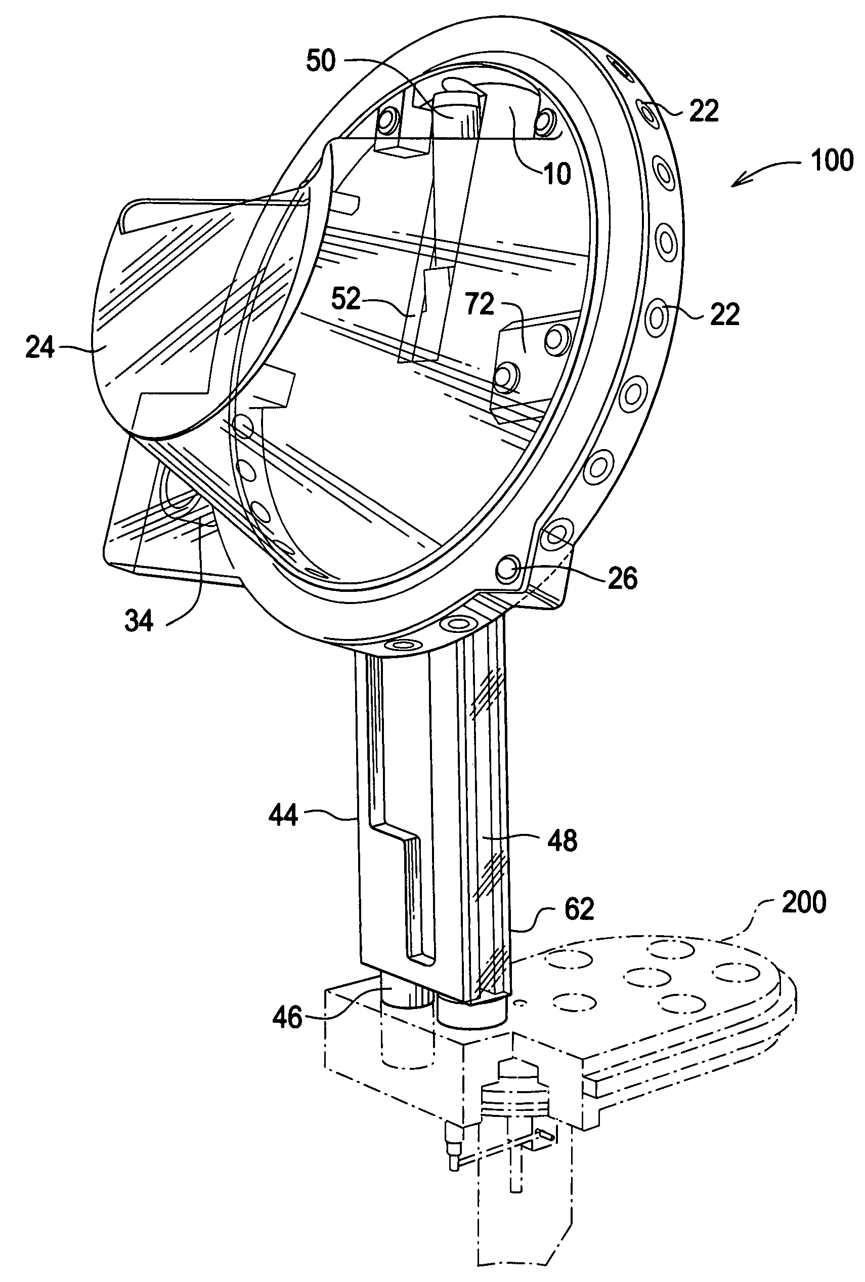
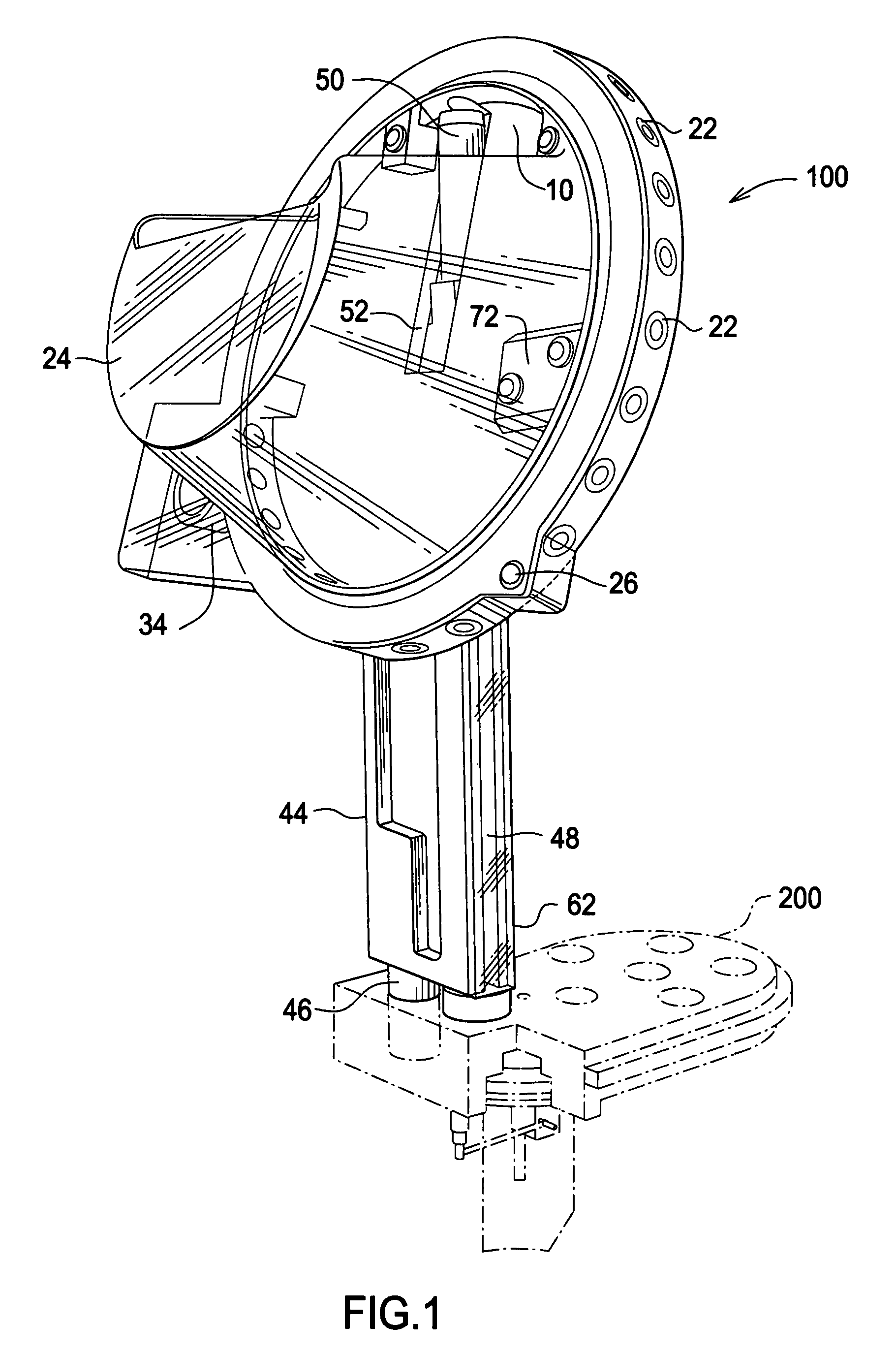
[0022]Referring now to FIG. 1, there is shown a rotary bullet feeder assembly 100 in accordance with the present invention, coupled to a toolhead assembly 200 that may be installed in a typical commercially available progressive cartridge reloading machine. The cartridge reloading machine, while utilizing applicant's important rotary bullet feeder assembly, does not form part of the present invention.

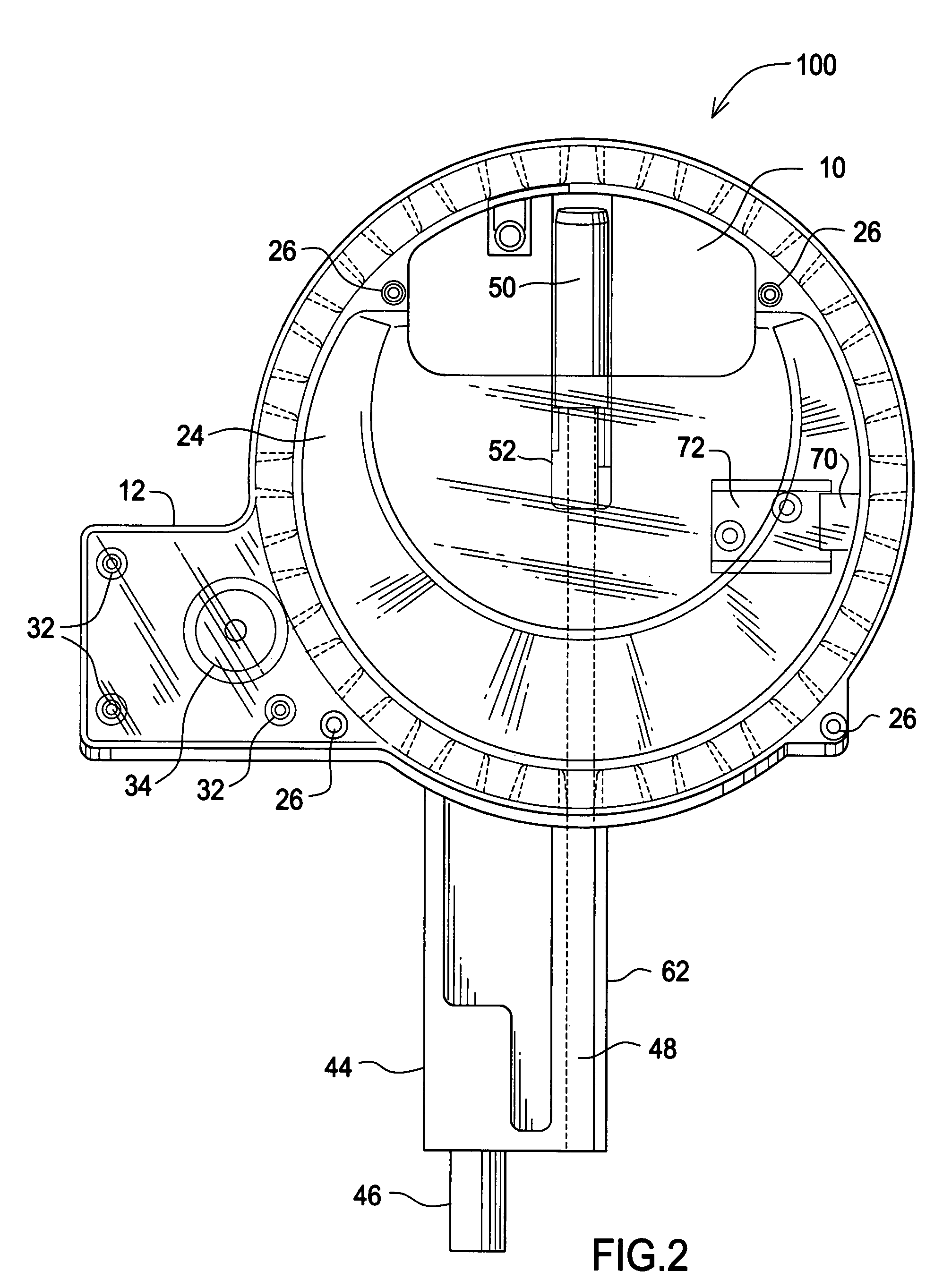
[0023]Referring additionally to FIGS. 2-7, bullet feeder assembly 100 includes a generally circular flat base plate 10 having a flange portion 12 extending to the left thereof. Base plate 10 may be fabricated of aluminum or any other rigid material. A low voltage reversible DC motor 30 of the type readily commercially available is conventionally mounted on the rear surface of flange portion 12 of base plate 10 by means of bolts or other conventional mounting hardware at locations 32. A circular raised boss 14 is formed on the front surface of base plate 10 and is spaced inwardly uniform...


PUM


Abstract

Rotary bullet feeder and toolhead assemblies for use with commercially available progressive cartridge reloading machines automatically supply correctly-oriented bullets to a bullet seating die position thereof. The rotary bullet feeder assembly randomly collects hoppered bullets in a desired orientation in a multiplicity of bullet pockets formed along the peripheral edge of a rotating bullet feed ring. An arcuate bullet wall prevents gravitational release of the bullets contained in the bullet pockets until each of the bullet pockets, in turn, reaches the apex point along its circular route of travel, at which point an opening in the bullet wall allows a bullet to fall into a bullet guide for gravitational descent to a toolhead assembly. The toolhead assembly includes a toolhead plate for receiving the rotary bullet feeder assembly and a flat circular bullet feedwheel mounted for rotation on the underside of the toolhead plate. The bullet feedwheel includes a plurality of bullet feed holes equidistantly arranged in a circle proximate the peripheral edge of the bullet feedwheel. An indexing mechanism, positioned beneath the bullet feedwheel, serves to incrementally rotate or index the bullet feedwheel in response to each user actuation of the handle of the cartridge reloading machine. Each incremental indexing rotation of the bullet feedwheel serves to sequentially advance each bullet feed hole containing a bullet received from the rotary bullet feeder assembly into alignment with a conventional seating die positioned in the toolhead plate.

Description

BACKGROUND AND SUMMARY OF THE INVENTION[0001]This invention relates generally to ammunition reloading machines and, more particularly, to a rotary bullet feeder assembly and a toolhead assembly for enhancing the operation of such ammunition reloading machines.[0002]Reloading one's ammunition began years ago in an effort by shooters to research and develop special ammunition, rather than settle for off-the-shelf ammo. An ammunition cartridge includes a cartridge case, a primer, a charge of smokeless powder, and a bullet. After a cartridge has been fired and discharged, it cannot be reused. As a result, those who frequent the shooting ranges accumulate buckets of used empty brass cartridge cases. In the early days, cartridge reloading was accomplished by a time consuming handload process. This process involved 1) resizing the used empty cases so that they will again fit into the firearm chamber; 2) removing the old primer from the case; 3) cleaning the case; 4) reforming the mouth of ...

Claims


Application Information

Patent Timeline
IPC IPC(8): F42B33/00
CPCF42B33/00F42B33/001F42B33/002F42B33/004
Inventor GONZALEZ, XAVIER G.
Owner GONZALEZ XAVIER G
Why Eureka
Try Eureka