Flat display panel module and flat display apparatus

a technology for flat display panels and flat displays, applied in the direction of electrical apparatus casings/cabinets/drawers, identification means, instruments, etc., can solve the problems of difficult escape of force transmitted to the luminescent glass in the vicinity of the attaching portion, panel breakage, etc., to prevent glass breakage, buffer effect, absorb

Inactive Publication Date: 2009-06-30
MAXELL HLDG LTD
View PDF31 Cites 30 Cited by
  • Summary
  • Abstract
  • Description
  • Claims
  • Application Information

AI Technical Summary

Benefits of technology

[0009]The present invention has been made in consideration of the above problem, and accordingly an object of the present invention is to provide a technique for effectively buffering, absorbing, or distributing a force applied to the panel of an FDP module, especially a stress concentrating locally in the vicinity of the attaching portion of the base chassis and the casing, thereby improving impact resistance performance of the panel and enhancing long-term reliability thereof.
[0024]Effects obtained from the representative ones of the inventions disclosed in the present application will be briefly explained as follows. According to the present invention, since the force applied to the panel of the FDP module is effectively buffered, absorbed, or distributed, it is possible to improve the impact resistance performance of the panel and prevent breakage of the glass or the like to increase long-term reliability of the FDP.
[0025]Further, according to items (3) and the like as described above, both of the impact resistance performance and the heat dissipation performance of the panel can be attained. Also especially, according to items (4) and the like as described above, the impact resistance performance can be enhanced by a synergetic effect with the filter. Moreover, especially, according to items (5) and the like, an elastic structure can be realized without involving an increase in the number of parts and by increasing no costs or very slightly costs.

Problems solved by technology

Therefore, it is difficult to make a force transmitted to the luminescent glass in the vicinity of the attaching portion escape.
That is, a problem is such that the impact resistance performance in the vicinity of the attaching portion is inferior to that in the vicinity of an area where the attaching portion does not exist, which results in a possibility that the panel will be broken.

Method used


Image

  • Flat display panel module and flat display apparatus
  • Flat display panel module and flat display apparatus
  • Flat display panel module and flat display apparatus

Examples


first embodiment

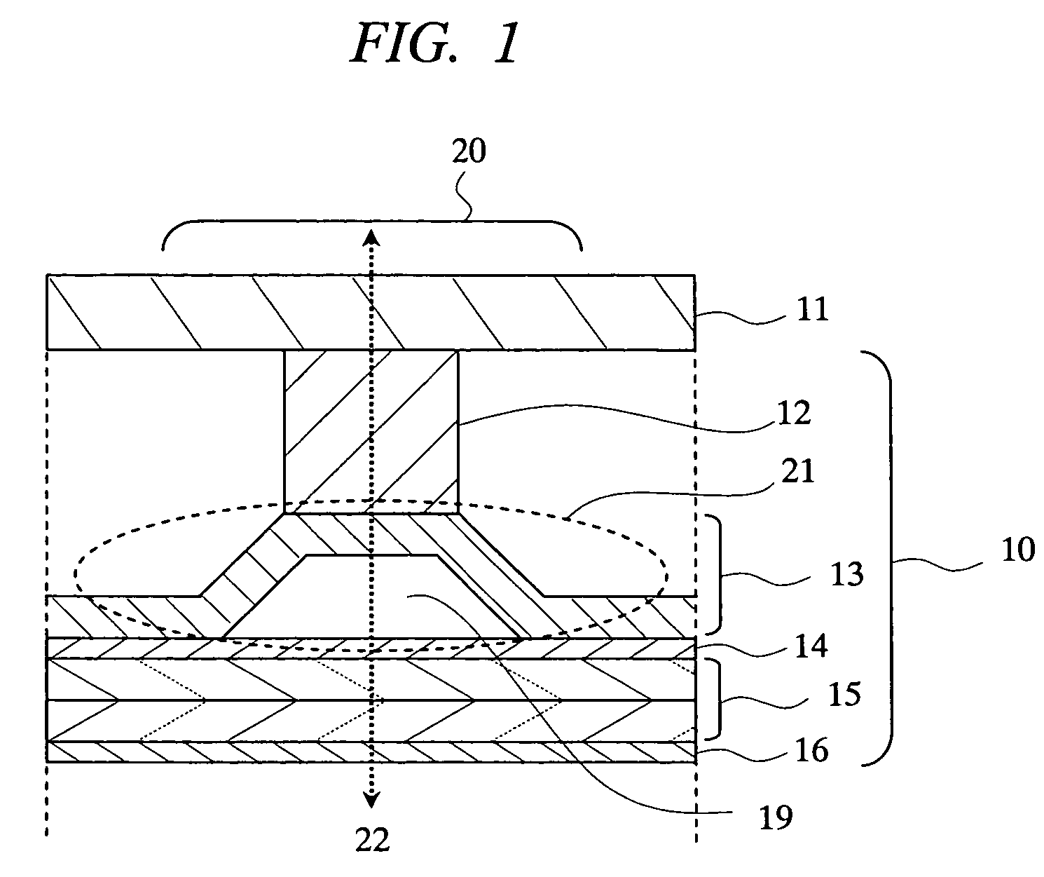
[0035]A first embodiment provides a structure including an FDP module and a PDP serving as a flat display apparatus, wherein the embodiment has, as an outline, a dish-shaped spring structure portion in a base chassis area corresponding to an attaching portion for a PDP module and a plasma display apparatus casing.

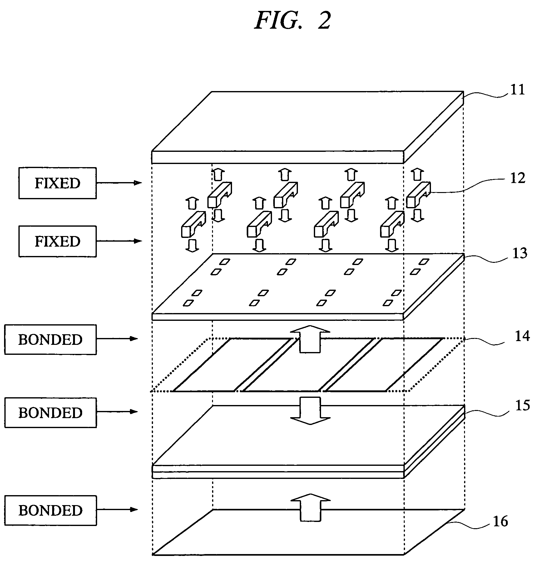
[0036]FIG. 1 through FIG. 6 show structures of a PDP module (10) and a plasma display apparatus according to the first embodiment of the present invention. FIG. 1 shows a main structure of this plasma display apparatus and illustrates a cross-sectional structure in the vicinity of an attaching portion (20) for the PDP module (10) and the casing (11). FIG. 2 shows a disassembled structure in assembly (manufacture) of the PDP module (10) and in assembly of the PDP module (10) and the casing (11). FIG. 3 shows a structure of an attaching area of a rear surface of a base chassis (13) in the PDP module (10). FIG. 4 shows a structure for bonding a PDP (15) and the base chassis (1...

second embodiment

[0061]Next, a second embodiment will be explained. FIG. 7 shows a structure of a PDP module and a plasma display apparatus according to a second embodiment of the present invention. The second embodiment has a structure as a portion corresponding to a spring structure portion 21 in the above-mentioned attaching part 20, that is, a structure in which a spring part 71 is connected and fixed between the base chassis 13 and the connecting part 12. The other structures in the second embodiment are the same as those in the first embodiment. In the first embodiment, the spring structure portion 21 is formed as a portion of the structure body of the base chassis 13. However, the second embodiment has a structure providing directly and interposing the spring part 71.

[0062]The spring part 71 has elasticity in the direction of the center axis 22, that is, may be called an impact absorbing material. The spring part 71 may be more particularly constituted from various kinds of structures. Regard...

third embodiment

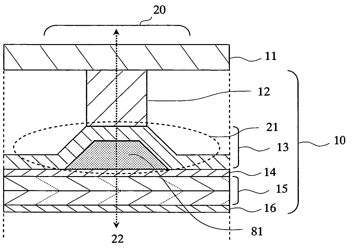
[0064]Next, a third embodiment will be explained. FIG. 8 shows a structure of a PDP module and a plasma display apparatus according to a third embodiment of the present invention. The third embodiment further has a constitution in the attaching portion 20 with the same structure as that in the first embodiment, that is, a constitution in which a filling material (highly thermal conductive gel material) 81 is provided in the space 19 in the spring structure portion 21 to attain both of impact resistance performance and heat dissipation performance. The other constitutions in the third embodiment are the same as those in the first embodiment.

[0065]The filling material 81 is a gel material, liquid, or the like that has a high thermal conductivity at least as compared with air. In the case where air exists in the space 19 in the first embodiment, since heat thermal conductivity of air is low, the heat dissipation performance of the attaching portion 20 is slightly inferior. However, in ...


PUM

PropertyMeasurementUnit
angleaaaaaaaaaa
angleaaaaaaaaaa
angleaaaaaaaaaa

Abstract

A technique for improving impact resistance performance of a panel is provided in a module or display apparatus with a flat display panel. In a PDP module, a filter is bonded onto a front surface side of a PDP, and a base chassis is bonded to a rear surface side with a two-sided tape. In an attaching portion for the base chassis and a casing, a spring structure portion having a sloped portion and a space is provided in an area of the base chassis so as to correspond to a connecting part of the casing. Impact to glass of the PDP is buffered to an impact force in a direction vertical to a surface of the PDP due to a spring property of the spring structure portion.

Description

CROSS-REFERENCE TO RELATED APPLICATION[0001]The present application claims priority from Japanese patent application No. JP 2005-213200 filed on Jul. 22, 2005, the content of which is hereby incorporated by reference into this application.BACKGROUND OF THE INVENTION[0002]The present invention relates to a module (hereinafter referred to as “FDP module”) including a flat display panel (hereinafter referred to as “FDP”) such as a plasma display panel (hereinafter referred to as “PDP”), and to a flat display apparatus (thin video display apparatus) such as a plasma display apparatus including the same module. It relates, more specifically, to a technique of a packaging structure and the like concerning impact resistance performance of an FDP (hereinafter simply referred to also as “panel”).[0003]In a plasma display apparatus, a PDP and a chassis serving as a base thereof (base chassis) are firmly fixed substantially entirely with an adhesive layer such as a two-sided tape, and configur...

Claims


Application Information

Patent Timeline
Patent Type & Authority Patents(United States)
IPC IPC(8): G06F1/20G02F1/1333G09F9/00
CPCH05K5/02H01J11/34
Inventor TANOKUCHI, AKITOSUZUKI, KUNINORIIMAOKA, KAZUO
Owner MAXELL HLDG LTD
Why Eureka
Try Eureka