Multilevel converter arrangement

a converter arrangement and multi-level technology, applied in the field of power converters, can solve problems such as integration, and achieve the effect of cost-effectiveness

Inactive Publication Date: 2009-06-30
ABB (SCHWEIZ) AG
View PDF8 Cites 10 Cited by
  • Summary
  • Abstract
  • Description
  • Claims
  • Application Information

AI Technical Summary

Benefits of technology

[0008]A cost-effective way of controlling the power semiconductor devices at the various levels of a medium voltage multilevel converter is disclosed based on a multilevel converter arrangement and a use thereof.

Problems solved by technology

In these places however, a conventional transformer with a nominal frequency of 16.7 Hz or 50 Hz causes integration problems due to its high weight and large volume.
As the gate-drive circuit including the insulation boundary is part of one single integrated gate-drive unit, insulation problems due to space restrictions or dielectric requirements prohibits a straightforward application of this gate-drive unit to higher voltage levels beyond approximately 10 kV RMS.

Method used


Image

  • Multilevel converter arrangement
  • Multilevel converter arrangement
  • Multilevel converter arrangement

Examples


Embodiment Construction

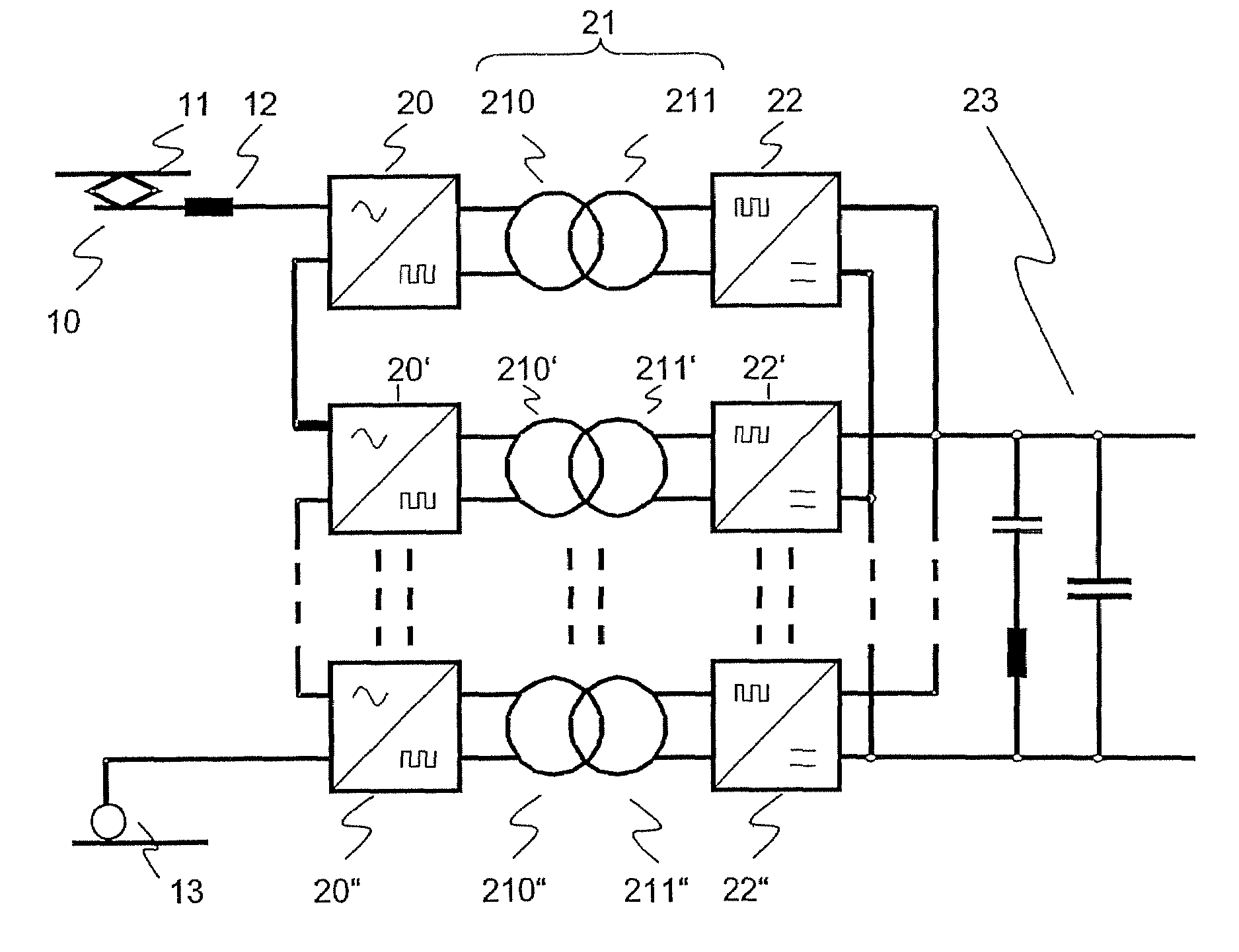
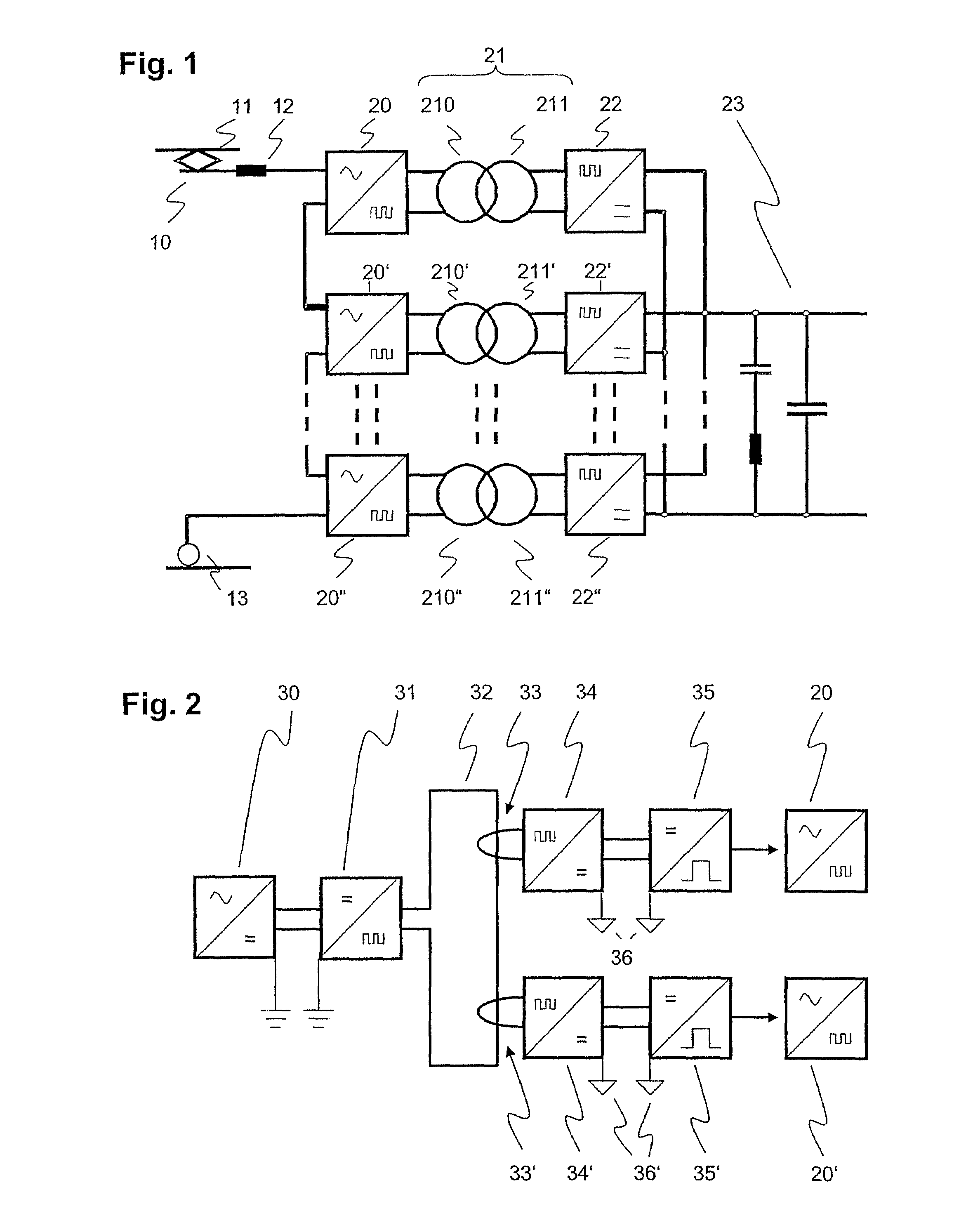
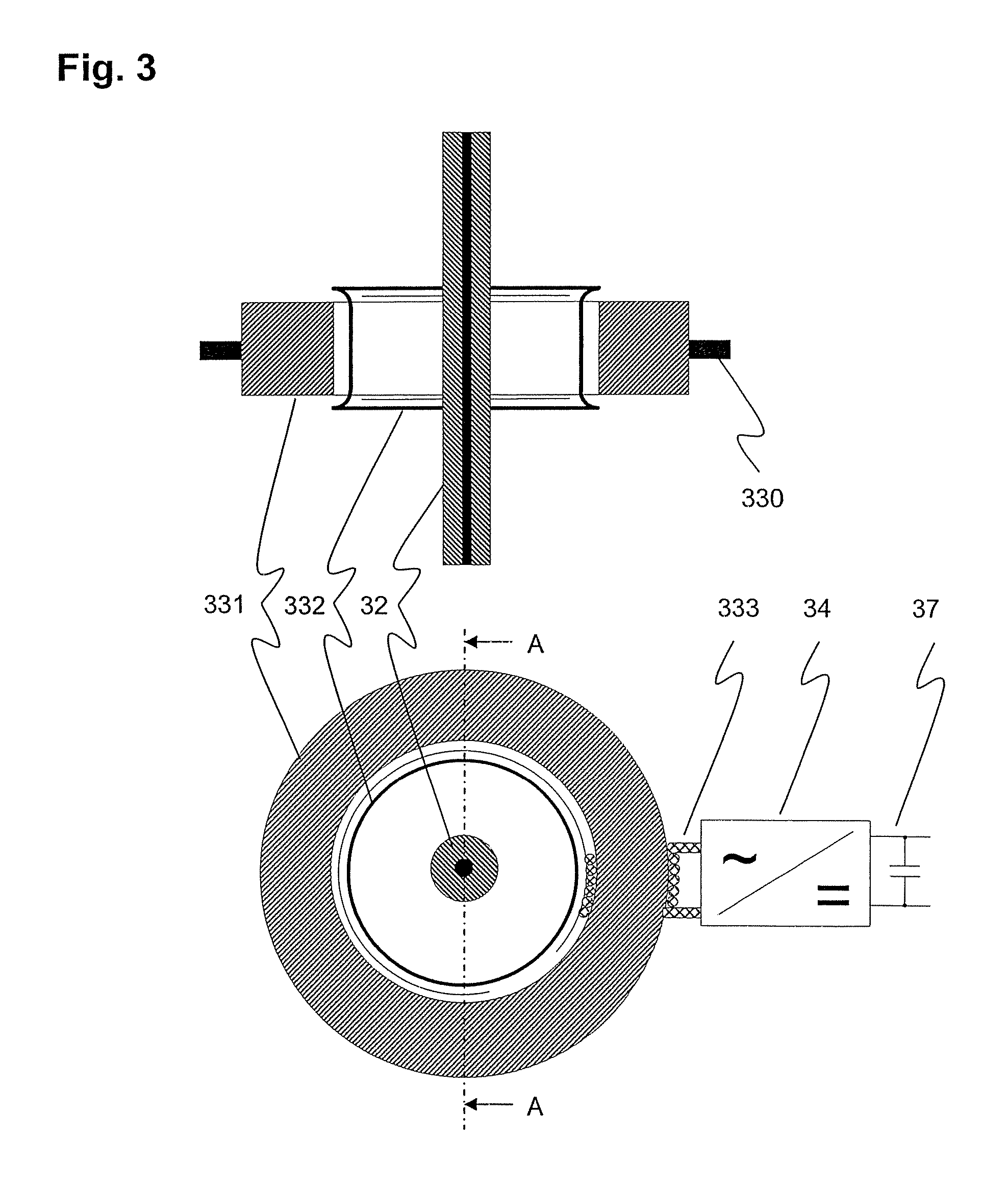
[0015]In the proposed exemplary arrangement, the gate-drive is provided with the necessary power by means of a power loop with a power-loop emitter and a power-loop receptor. The emitter and receptor are located in different housings and connected via a power-loop conductor that is at least partially exterior to both housings. By means of a current transformer inductively coupling the conductor to the emitter or receptor, the power-loop also provides for electrical insulation between the emitter and the receptor. The fact that emitter and receptor are remote or physically distant from each other, and thus not integrated into one common gate-drive housing, offers greater flexibility in the positioning and design of the galvanic separation between the emitter and the receptor or the supplied gate-drive, respectively. In particular, the local voltages of converter levels ranging up to the supply voltage of e.g. 21 kV RMS of the multilevel converter can thus be insulated from the global...


PUM


Abstract

A power loop has a power-loop emitter and a power-loop receptor located in different housings and connected via a power-loop conductor that is at least partially exterior to both housings. By means of a current transformer inductively coupling the conductor to the emitter or receptor, the power-loop also provides for electrical insulation between the emitter and the receptor. The emitter and receptor being distant from each other offers greater flexibility in the positioning and design of the galvanic separation between the emitter and the receptor or the supplied gate-drive, respectively. For example, the local voltages of converter levels ranging up to the supply voltage of e.g. 21 kV RMS of the multilevel converter can thus be insulated from the global earth potential of the power-loop emitter. Several power-loop receptors can be coupled to the same power-loop conductor to be fed by the same power-loop emitter.

Description

RELATED APPLICATIONS[0001]This application claims priority under 35 U.S.C. §119 to EP Application 05405464.8 filed in Europe on Aug. 3, 2005, and as a continuation application under 35 U.S.C. §120 to PCT / CH2006 / 000398 filed as an International Application on Jul. 31, 2006 designating the U.S., the entire contents of which are hereby incorporated by reference in their entireties.TECHNICAL FIELD[0002]The disclosure relates to the field of power converters, and more particular to medium voltage multilevel power electronic converters for single-phase traction applications. It departs from a multilevel converter arrangement with a gate-drive unit and more than two converter levels.BACKGROUND INFORMATION[0003]Electric railway vehicles such as locomotives or rail coaches powered by an alternating-current (AC) supply line use a traction transformer and an AC / DC converter for converting the high voltage (15 kV or 25 kV) of the supply line to a direct-current (DC) link voltage of a few kV and...

Claims


Application Information

Patent Timeline
Patent Type & Authority Patents(United States)
IPC IPC(8): H02M7/08
CPCH02M7/003H02M7/483
Inventor STEFANUTTI, PHILIPPEHUGO, NICOLASMEYSENC, LUCNOISETTE, PHILIPPEPIAZZESI, ALICE
Owner ABB (SCHWEIZ) AG
Why Eureka
Try Eureka