Interference-based routing in a wireless mesh network

a wireless mesh network and interference-based technology, applied in the field of wireless communications, can solve the problems of high error rate, long time to transmit packets, power/interference limitations, etc., and achieve the lowest cumulative “cost” and low data rate. , the effect of high error ra

Active Publication Date: 2009-06-30
TELEFON AB LM ERICSSON (PUBL)
View PDF3 Cites 285 Cited by
  • Summary
  • Abstract
  • Description
  • Claims
  • Application Information

AI Technical Summary

Benefits of technology

[0005]In open shortest path first (OSPF) routing, each wireless node maintains an identical database describing the network topology. From this database, a routing table is calculated by constructing a shortest path tree. The shortest path is that with the lowest cumulative “cost.” For a radio link or hop, the “cost” may be measured as the inverse of the expected data rate over that radio hop. As a result, low data rates are high cost because they result in longer times to transmit packets. OSPF was initially designed for fixed networks, but wireless routing protocol (WRP) and dynamic source routing (DSR) are similar in their route selection approach for wireless networks.
[0006]Wireless ad hoc networks must deal with certain limitations associated with the wireless communications medium including power / interference limitations, low bandwidth, and high error rates. Because wireless network nodes are typically battery-operated and because the capacity of a radio communications network is limited by the shared spectrum, routing protocols that attempt to find minimum energy routing path are of particular interest. Energy efficient routing schemes can greatly reduce energy consumption at the nodes, leading to longer battery life, as well as improve the network capacity by reducing the interference in the network. Table-driven routing schemes are generally more expensive in terms of energy consumption as compared to on-demand schemes because of the large overhead required to maintain the various tables. But minimum energy routing techniques should not only be focused on battery saving of the mobile nodes. Such routing algorithms should also try to improve network capacity.
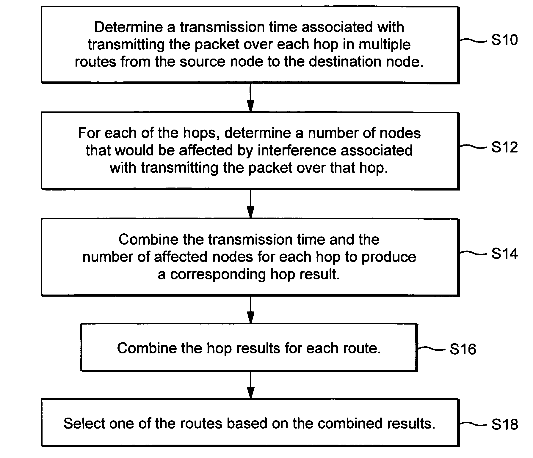
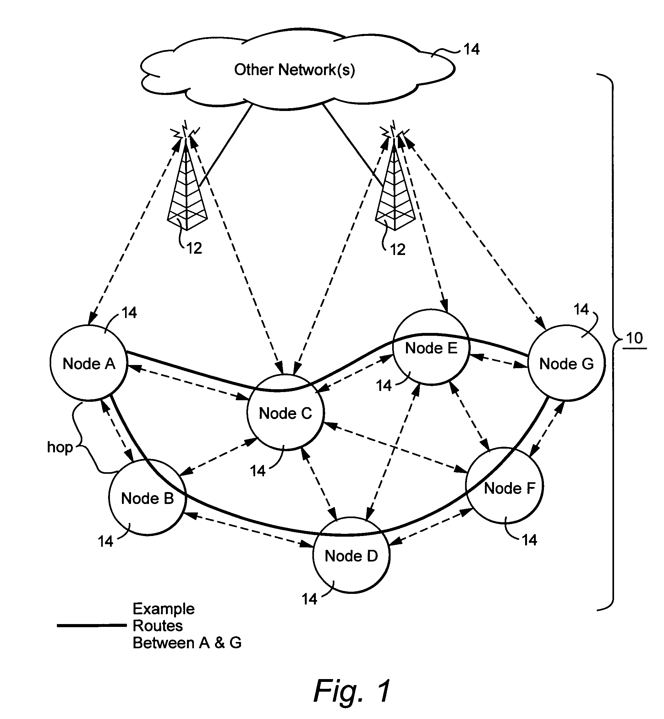
[0008]The inventors recognized that there are several factors that must be considered to obtain an optimal energy routing scheme. First, it is important to reduce the number of nodes refraining from transmitting over the common frequency due to a busy indication, e.g., a clear channel assessment (CCA) busy indication. Second, it is also important to reduce the length of time that each node must wait before it can transmit over the common channel. Although selecting the shortest length path as the shortest time delay path may improve battery saving, it may not optimize the network capacity. Wireless networks are interference limited. Transmission power is in most scenarios not equal to the interference caused by a particular transmission at a particular power. Indeed, nodes may be affected by transmission-based interference even if they are not within range / communication distance of the transmitting node, i.e., the nodes are still within interference distance.

Problems solved by technology

As a result, low data rates are high cost because they result in longer times to transmit packets.
Wireless ad hoc networks must deal with certain limitations associated with the wireless communications medium including power / interference limitations, low bandwidth, and high error rates.
Table-driven routing schemes are generally more expensive in terms of energy consumption as compared to on-demand schemes because of the large overhead required to maintain the various tables.
Although selecting the shortest length path as the shortest time delay path may improve battery saving, it may not optimize the network capacity.
Wireless networks are interference limited.
Indeed, nodes may be affected by transmission-based interference even if they are not within range / communication distance of the transmitting node, i.e., the nodes are still within interference distance.
Such signaling updates, particularly if frequently transmitted, drain the power of the battery-operated nodes and increase the interference in the network.
So transmission energy is not an adequate measurement of the caused interference.

Method used


Image

  • Interference-based routing in a wireless mesh network
  • Interference-based routing in a wireless mesh network
  • Interference-based routing in a wireless mesh network

Examples


Embodiment Construction

[0023]In the following description, for purposes of explanation and not limitation, specific details are set forth, such as particular components, electronic circuitry, techniques, protocols, standards, etc. in order to provide an understanding of the described technology. For example, one advantageous application is to wireless local area networks that follow the IEEE 802.11 standard. But other standards and other types of network are also applicable, e.g., Bluetooth PANs. Further, it will be apparent to one skilled in the art that other embodiments may be practiced apart from the specific details. In other instances, detailed descriptions of well-known methods, devices, techniques, etc. are omitted so as not to obscure the description with unnecessary detail. Individual function blocks are shown in the figures. Those skilled in the art will appreciate that the functions of those blocks may be implemented using individual hardware circuits, using software programs and data in conju...


PUM


Abstract

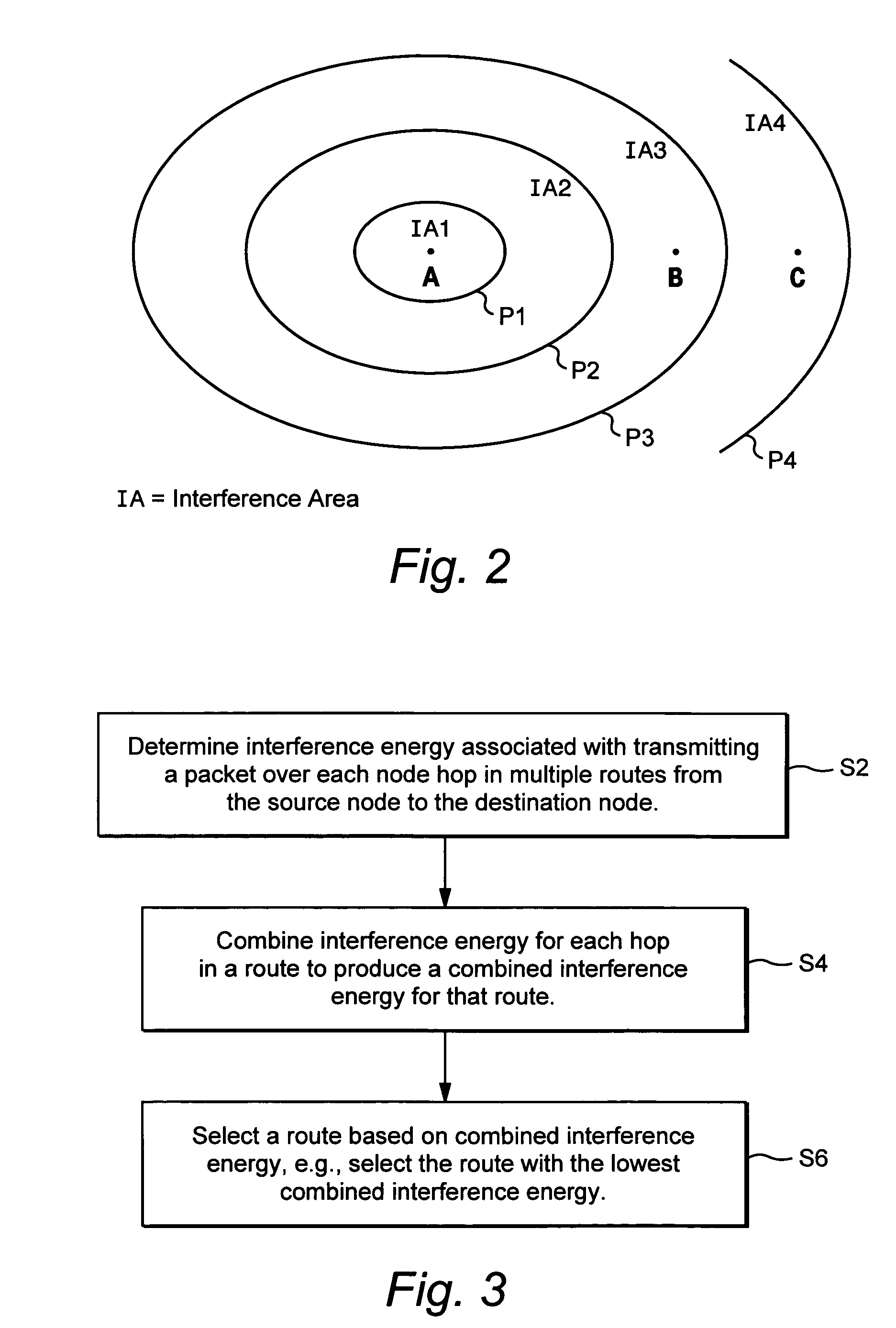
Route selection through a wireless mesh network between a source node and a destination node is based on minimizing generated interference in order to increase the capacity of the network. An interference energy associated with transmitting a packet over each hop in multiple routes from the source node to the destination node is determined. The interference energy for each hop is combined to generate a combined interference energy for each route. One of the routes is selected based on the combined interference energy determined for each route.

Description

TECHNICAL FIELD[0001]The technical field relates generally to wireless communications, and more particularly, to selecting a route through a wireless mesh network.BACKGROUND AND SUMMARY[0002]Wireless networks have become increasingly important and popular because mobility is supported along with many of the sophisticated applications offered by fixed wired networks. Wireless networks include traditional cellular networks with radio base stations coupled to a radio network infrastructure. A mobile terminal communicates with one or more base stations within range, and as the mobile moves out of range, a handover procedure to another base station may be performed to maintain continuous communication. Another type of wireless network is a mesh network. A mesh network handles many-to-many connections and is capable of dynamically optimizing these connections.[0003]Wireless mesh networks are commonly known as wireless “ad hoc” networks that usually consist of mobile, battery-operated comp...

Claims


Application Information

Patent Timeline
Patent Type & Authority Patents(United States)
IPC IPC(8): H04L12/407H04W40/16
CPCH04L45/00H04W40/16Y02B60/42Y02B60/50Y02D30/00Y02D30/70
Inventor SIMONSSON, ARNEPETTERSSON, JONAS
Owner TELEFON AB LM ERICSSON (PUBL)
Why Eureka
Try Eureka