Large effective area fiber

a fiber and effective area technology, applied in the field of optical fibers, can solve the problems of reducing non-linear optical effects, and affecting the performance of optical fibers with multi-layer cores/claddings,

Active Publication Date: 2009-06-30
CORNING INC
View PDF23 Cites 304 Cited by
  • Summary
  • Abstract
  • Description
  • Claims
  • Application Information

AI Technical Summary

Problems solved by technology

Generally, an optical waveguide fiber having a large effective area (Aeff) reduces non-linear optical effects, including self-phase modulation, four-wave-mixing, cross-phase modulation, and non-linear scattering processes, all of which can cause degradation of signals in high powered systems.
On the other hand, an increase in effective area of an optical waveguide fiber typically results in an increase in macrobending induced losses which attenuate signal transmission through a fiber.
The macrobending losses become increasingly significant over long (e.g., 100 km, or more) distances (or spacing between regenerators, amplifiers, transmitters and / or receivers.
Unfortunately, the larger the effective area of a conventional optical fiber is, the higher the macrobend induced losses tend to be.

Method used


Image

  • Large effective area fiber
  • Large effective area fiber
  • Large effective area fiber

Examples


Embodiment Construction

[0032]Additional features and advantages of the invention will be set forth in the detailed description which follows and will be apparent to those skilled in the art from the description or recognized by practicing the invention as described in the following description together with the claims and appended drawings.

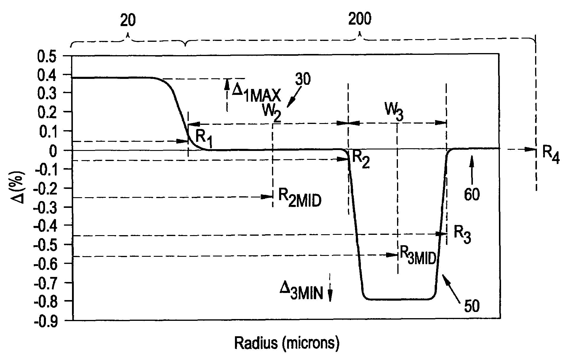
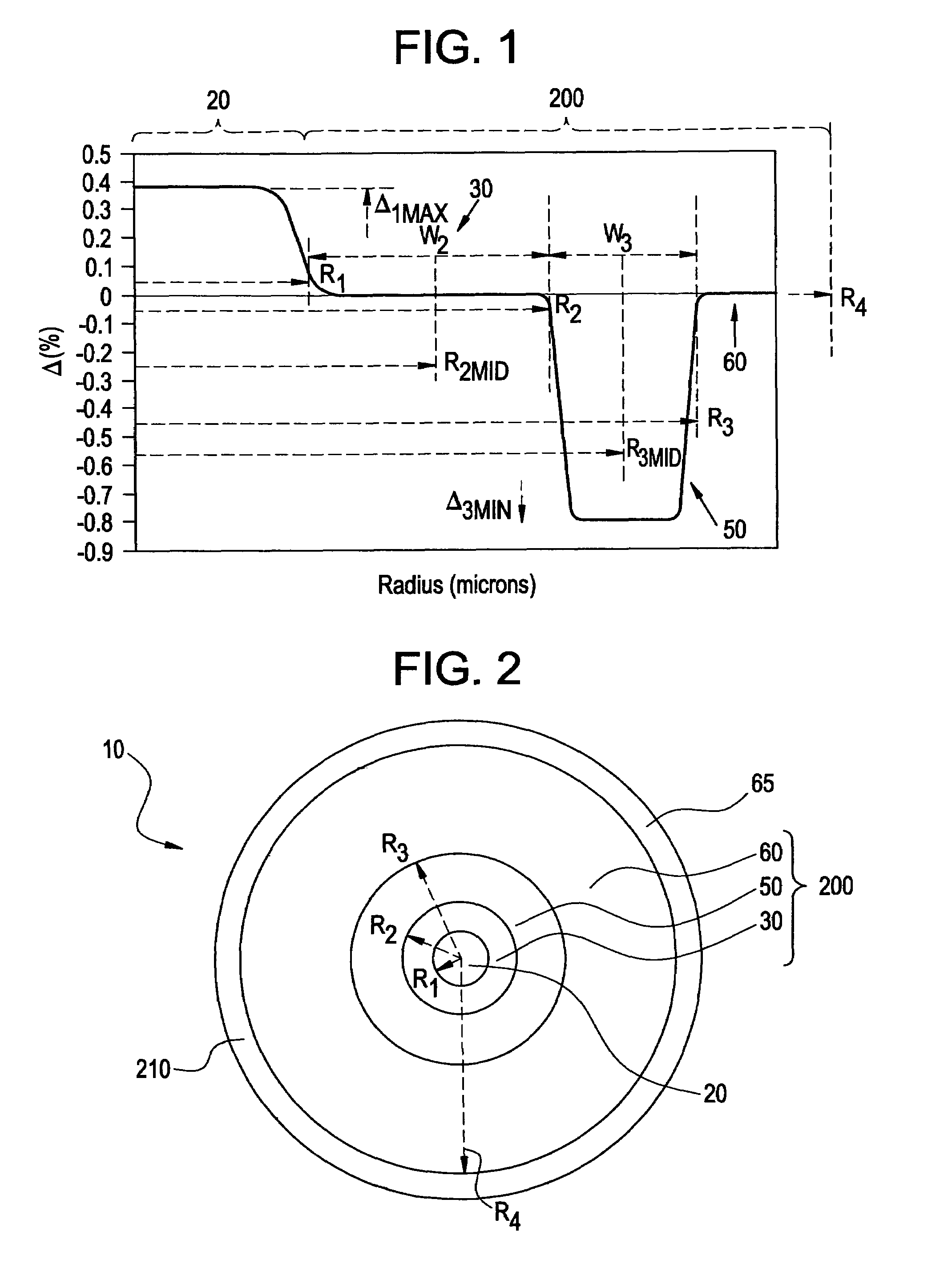
[0033]The “refractive index profile” is the relationship between refractive index or relative refractive index and waveguide fiber radius.

[0034]The “relative refractive index percent” is defined as Δ %=100×(ni2−nc2) / 2ni2, where ni is the maximum refractive index in region i, unless otherwise specified, and nc is the average refractive index of the third annular region 60 (outer region) of the cladding. As used herein, the relative refractive index is represented by Δ and its values are given in units of “%”, unless otherwise specified. In cases where the refractive index of a region is less than the average refractive index of the third annular region 60, the relative i...


PUM


Abstract

An optical fiber according to an embodiment of the present invention comprises: a glass core extending from a centerline to a radius R1 wherein R1 is greater than about 5 μm; a glass cladding surrounding and in contact with the core, the cladding comprising: (i) a first annular region extending from the radius R1 to a radius R2, the first annular region comprising a radial width, W2=R2−R1, (ii) a second annular region extending from the radius R2 to a radius R3, and comprising a radial width, W3=R3−R2, and (iii) a third annular region surrounding the second annular region and extending from the radius R3 to an outermost glass radius R4; wherein the core comprises a maximum relative refractive index, Δ1MAX, relative to the third annular region, and wherein Δ1MAX is greater than about 0.1% and less than about 0.3%; the first annular region has a refractive index delta Δ2(r) is less than about 0.025%; wherein the second annular region comprises a minimum relative refractive index, Δ3MIN, relative to the third annular region;wherein Δ1MAX>Δ2MAX>Δ3MIN, and Δ2MIN>Δ3MIN<0; andwherein the core and the cladding provide a fiber with cable cutoff less than 1500 nm, and an effective area at 1550 nm greater than 95 μm2 and bend loss of ≦0.5 dB / turn on a 20 mm diameter mandrel.

Description

[0001]This application claims the benefit of U.S. Provisional Application No. 60 / 927,989 filed May 7, 2007, entitled “Large Effective Area Fiber”.BACKGROUND OF THE INVENTION[0002]1. Field of the Invention[0003]The present invention relates generally to optical fiber, and particularly optical fibers which have large effective area and low bend loss at 1550 nm.[0004]2. Technical Background[0005]Optical amplifier technology and wavelength division multiplexing techniques are typically required in telecommunication systems that provide high power transmissions for long distances. The definition of high power and long distances is meaningful only in the context of a particular telecommunication system wherein a bit rate, a bit error rate, a multiplexing scheme, and perhaps optical amplifiers are specified. There are additional factors, known to those skilled in the art, which have impacted upon the definition of high power and long distance. However, for most purposes, high power is an o...

Claims


Application Information

Patent Timeline
Patent Type & Authority Patents(United States)
IPC IPC(8): G02B6/036
CPCG02B6/0365G02B6/02019
Inventor BICKHAM, SCOTT ROBERTSONBOOKBINDER, DANA CRAIGCHEN, XINLI, MING-JUNMISHRA, SNIGDHARAJ KUMARNOLAN, DANIEL ALOYSIUS
Owner CORNING INC
Why Eureka
Try Eureka