Fiber optic auxiliary lighting system

a fiber optic and auxiliary lighting technology, applied in the direction of optical signalling, electric lighting with batteries, diffusing elements, etc., can solve the problems of limited acceptance of efforts, insufficient intensity, and inability to meet the needs of low-intensity vehicle body lighting

Inactive Publication Date: 2009-07-07
INT AMERICA
View PDF16 Cites 40 Cited by
  • Summary
  • Abstract
  • Description
  • Claims
  • Application Information

AI Technical Summary

Benefits of technology

[0006]A lighting device is provided that includes a housing containing a light emitting portion of a light emitting diode and a terminus of a fiber optic bundle such that light emission from the light emitting diode is communicated along the optical fibers. The fiber optic bundle has a flattened distal portion with a cross-sectional array of layers of optical fibers. A diffusing layer is attached to the fiber optic bundle overlying the flattened distal portion. The lighting device, upon being overlaid with a graphic and surrounded by a frame through which the graphic is visible, provides a vehicle lighting assembly securable to a vehicle substrate. The vehicle light assembly is particularly well suited for vehicle exterior badging, kick plates and vanity lighting within the vehicle passenger compartment.

Problems solved by technology

Low intensity vehicle body lighting was largely impractical with incandescent bulbs owing to problems associated with high vertical profiles and heat management.
However, such efforts have met with limited acceptance owing to intensity variation along the length of a feature such as a vehicle door kick plate.
Unfortunately, the fiber optic bundle outer layers obscure emission from fiber optics within the interior of the bundle and as a result provide insufficient intensity to backlight a transparent or translucent overlay positioned parallel to the fiber optic bundle.
Electroluminescent backlighting in a vehicle context has been limited to a narrow range of applications perceived to be of high value owing to the stringent electrical input requirements, material costs and susceptibility to environmental degradation.

Method used


Image

  • Fiber optic auxiliary lighting system
  • Fiber optic auxiliary lighting system
  • Fiber optic auxiliary lighting system

Examples


Embodiment Construction

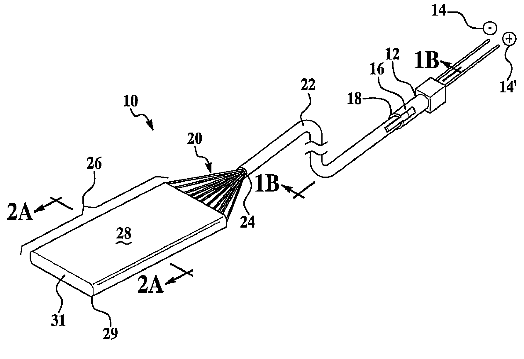
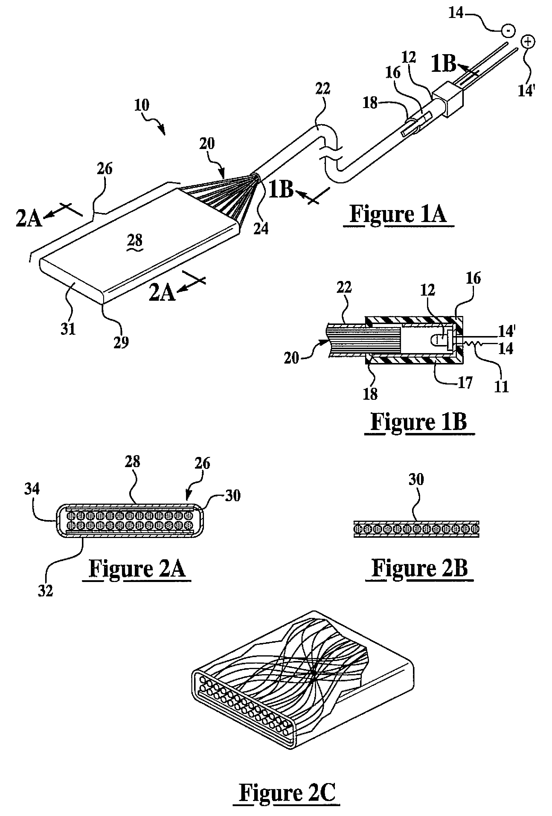
[0031]The present invention has utility as a backlit lighting system. The dimensional and performance properties of an inventive lighting device are particularly well suited for vehicle passenger compartment and vehicle exterior trim illumination. The high optical uniformity of the light flux emitted orthogonal to a fiber axis is achieved by flattening a fiber optic bundle receiving light from a light emitting diode by flattening the fiber optic bundle. Insertion of a diffusion coating intermediate between a fiber optic bundle and a viewing vantage point affords still more uniform optical flux gradients across a flattened portion of an optical fiber bundle receiving light emission from the light emitting diode proximal to a terminus of the fiber optic bundle. Light emission uniformity from the flattened bundle is enhanced by placing a diffusion layer intermediate between the fiber optic bundle and the direction of viewing. A backing layer is optionally applied to the rearmost surfac...


PUM

PropertyMeasurementUnit
heightaaaaaaaaaa
heightaaaaaaaaaa
lengthaaaaaaaaaa

Abstract

A lighting device is provided that includes a housing containing a light emitting portion of a light emitting diode and a terminus of a fiber optic bundle such that light emission from the light emitting diode is communicated along the optical fibers. The fiber optic bundle has a flattened distal portion with a cross-sectional array of layers of optical fibers. A diffusing layer is attached to the fiber optic bundle overlying the flattened distal portion. The lighting device, upon being overlaid with a graphic and surrounded by a frame through which the graphic is visible, provides a vehicle lighting assembly securable to a vehicle substrate. The vehicle light assembly is particularly well suited for vehicle exterior badging, kick plates and vanity lighting within the vehicle passenger compartment.

Description

FIELD OF THE INVENTION[0001]The present invention in general relates to diffuse backlighting via a fiber optic bundle, and in particular to transmission of light emitting diode emission via fiber optics in the context of backlighting of vehicle plates.BACKGROUND OF THE INVENTION[0002]Low intensity lighting installations provide enhanced safety and decorative properties to a vehicle body or driver helmet. Low intensity vehicle body lighting was largely impractical with incandescent bulbs owing to problems associated with high vertical profiles and heat management. More recently, other approaches to backlighting vehicle body features have invoked direct lighting with a light emitting diode. U.S. Pat. No. 6,244,734 is representative of such efforts. However, such efforts have met with limited acceptance owing to intensity variation along the length of a feature such as a vehicle door kick plate. Intensity variations have been in part compensated for by a linear array of light emitting ...

Claims


Application Information

Patent Timeline
Patent Type & Authority Patents(United States)
IPC IPC(8): G09F13/18
CPCA42B3/044B60Q1/2673B60Q1/2676B60Q1/28B60Q1/302B60Q1/32B60Q3/004B60Q3/0216B60Q3/06G02B6/001B60Q1/323G02B6/0081G02B6/0051B60Q3/64B60Q3/217B60Q3/30B60Q1/325
Inventor GUILLERMO, VERNON
Owner INT AMERICA
Why Eureka
Try Eureka