Optically controlled microfluidic chip

a microfluidic chip and microfluidic technology, applied in the field of microfluidic retinal implants, can solve the problems of limited vision recovery, permanent damage to the photoreceptor, and ineffective treatment for most patients, and achieve the effect of reducing fluid emission, reducing emission, and precise and physiologically relevant manner

Inactive Publication Date: 2009-07-07
THE BOARD OF TRUSTEES OF THE LELAND STANFORD JUNIOR UNIV +1
View PDF7 Cites 19 Cited by
  • Summary
  • Abstract
  • Description
  • Claims
  • Application Information

AI Technical Summary

Benefits of technology

[0007]The present invention provides an optically controlled microfluidic chip that allows for controlled stimulation of neurons in a more precise and physiologically relevant manner. The chip is made of at least one unit or pixel, each of which constitutively emits fluid in the dark, and reduces emission of fluid in response to light. The individual pixels are capable of being individually controlled, thereby translating a spatial pattern of incident light into a spatial pattern of neuronal stimulation. Each pixel contains a housing, an aperture in the housing, and a reservoir containing fluid that is connected to the aperture. The aperture has a bottom, which is connected to the reservoir, and an exit, through which fluid emits out of the chip. The aperture is designed to allow continuous emission of fluid from the reservoir through the aperture when the pixel is in the dark. Each pixel also includes an optical control, which reduces the emission of fluid from the reservoir through the aperture in response to light.
[0008]In a preferred embodiment, the optical control is one or more photodiodes. Upon illumination, the photodiodes produce an electric field between an electrode at the base of the aperture (i.e. the end of the aperture that is connected to the reservoir) and an electrode on the top of the chip that is common to all of the pixels. In a particularly preferred embodiment, the common electrode is transparent. The electric field generated between the electrodes produces an electroosmotic flow through the aperture towards the reservoir, acting against the flow of fluid by diffusion. This results in a reduction of emission of fluid through the exit of the aperture in response to light. Thus, the present invention acts in a much more similar manner to retinal photoreceptors, with constitutive emission of fluid in the dark, and reduced emission of fluid in response to light. In addition, each pixel can be activated independently, providing a spatial pattern of stimulation in response to a spatial pattern of incident light, similar to normal vision.

Problems solved by technology

Currently, there is no effective treatment for most patients with AMD, a disease that often results in permanent damage to photoreceptors, but spares most retinal ganglion cells (RGCs) and second-order neurons, such as bipolar and horizontal cells.
Although these trials have demonstrated that vision is recoverable in a limited fashion, major challenges remain.
Due to the size and difficulties in placement of most available electrodes, imprecise electric field stimulation extending over long distances (several cell-body diameters) is used to depolarize neurons.
In addition, such methods often require excessive stimulation, which may be harmful, leading to inflammation of the stimulated region and gliosis.

Method used


Image

  • Optically controlled microfluidic chip
  • Optically controlled microfluidic chip
  • Optically controlled microfluidic chip

Examples


Embodiment Construction

[0013]The present invention provides an optically controlled microfluidic chip for controlled release of fluid. The following sections provide details on the components, dimensions, and manufacture of the chip.

Pixels

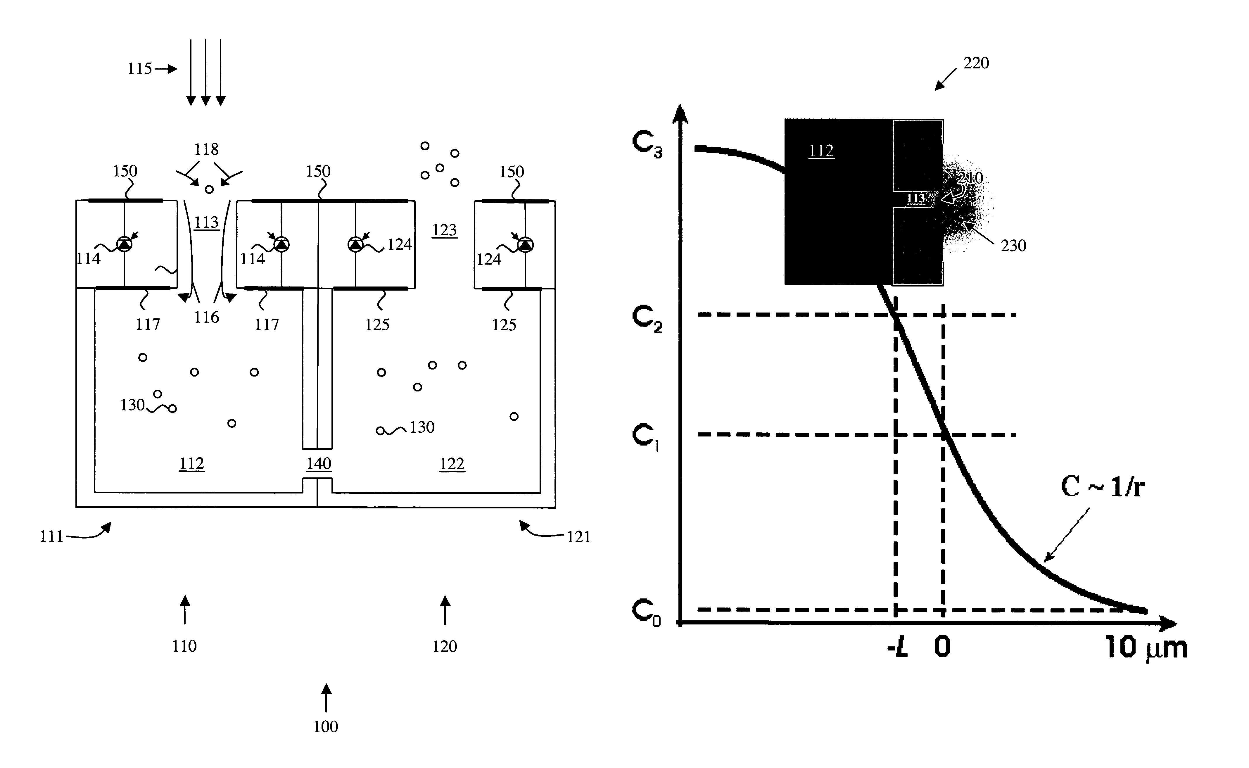
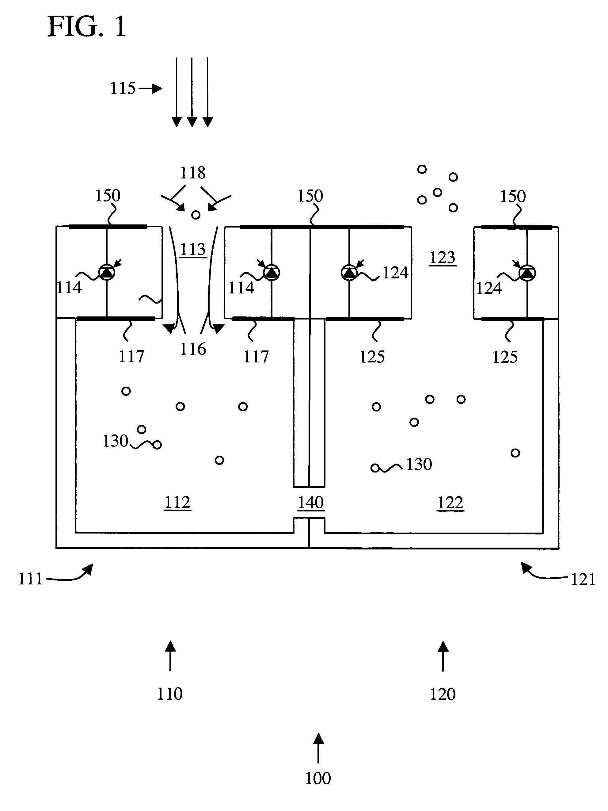
[0014]The optically controlled microfluidic chip is made of one or more units or pixels. Each pixel contains a housing, an aperture in the housing, and a reservoir containing fluid that is connected to the aperture. Each pixel also includes an optical control for limiting emission of fluid through the aperture in response to light. Each pixel may be independently controlled by light, such that a spatial pattern of incident light will translate into a spatially controlled reduction in emission of fluid.

[0015]FIG. 1 shows an example of an optically controlled microfluidic chip 100. Optically controlled microfluidic chip 100 has two pixels 110 and 120. Each pixel includes a housing (111 and 121, respectively), a reservoir (112 and 122, respectively), and an aperture (113 an...


PUM


Abstract

An optically controlled microfluidic chip is provided for administering a fluid to a neuronal site. The chip is made of at least one unit or pixel, each of which constitutively emits fluid in the dark, and reduces emission of fluid in response to light. The individual pixels are capable of being individually controlled, thereby translating a spatial pattern of incident light into a spatial pattern of neuronal stimulation. Each pixel contains a housing, an aperture in the housing, and a reservoir containing fluid that is connected to the aperture. The aperture is designed to allow continuous emission of fluid from the reservoir through the aperture when the pixel is in the dark. Each pixel also includes an optical control, which reduces the emission of fluid from the reservoir through the aperture in response to light.

Description

CROSS-REFERENCE TO RELATED APPLICATIONS[0001]This application claims priority from U.S. Provisional Patent Application No. 60 / 582,745, filed Jun. 23, 2004, which is incorporated herein by reference. This application is a continuation-in-part of U.S. patent application Ser. No. 10 / 184,210, filed Jun. 27, 2002 now U.S. Pat. No. 7,001,608, which claims priority from U.S. Provisional Patent Application No. 60 / 301,934, filed Jun. 29, 2001, which are incorporated herein by reference.FIELD OF THE INVENTION[0002]The present invention relates generally to micro-fabricated medical devices. More particularly, the invention relates to microfluidic retinal implants.BACKGROUND[0003]Age-related macular degeneration (AMD) is one of the most common forms of blindness in people over the age of 65. Currently, there is no effective treatment for most patients with AMD, a disease that often results in permanent damage to photoreceptors, but spares most retinal ganglion cells (RGCs) and second-order neur...

Claims


Application Information

Patent Timeline
Patent Type & Authority Patents(United States)
IPC IPC(8): A61M35/00
CPCA61F2/14A61N1/0543A61M5/14276A61M2205/0244A61N1/36046A61M2210/0612A61M2205/3306
Inventor PALANKER, DANIEL V.FISHMAN, HARVEY A.
Owner THE BOARD OF TRUSTEES OF THE LELAND STANFORD JUNIOR UNIV
Why Eureka
Try Eureka