Retrograde fixation technique with insert-molded interference screw
What is Al technical title?
Al technical title is built by PatSnap Al team. It summarizes the technical point description of the patent document.
a technology of interference screw and retrograde fixation, which is applied in the field of retrograde fixation of interference screw, can solve the problems of shortening the life of acl repair, difficult formation of femoral socket, and only securement of ligament graft at the bottom of tibial tunnel
Inactive Publication Date: 2009-07-07
ARTHREX
View PDF33 Cites 31 Cited by
Summary
Abstract
Description
Claims
Application Information
AI Technical Summary
This helps you quickly interpret patents by identifying the three key elements:
Problems solved by technology
Method used
Benefits of technology
[0009]A driver for the screw fits into a cannulation in the leading end of the screw. Preferably, the driver is cannulated to accept the length of suture extending from the bottom opening of the tibial tunnel, and has means for grasping the suture to assist the surgeon in pulling the interference screw into the top opening of the tibial tunnel. The screw is blind headed (not filly cannulated) to eliminate synovial fluid leak through the screw into the tibial tunnel.
Problems solved by technology
One drawback of the described tenodesis methods is that the ligament graft is secured only at the bottom of the tibial tunnel.
Consequently, the graft is free to move from side to side, resulting in a “windshield wiper” effect, during which the graft abrades against the upper rim of the tibial tunnel, shortening the life of the ACL repair.
However, forming a femoral socket is difficult without a tibial tunnel for insertion of a femoral guide and drill.
Method used
Image
Click on the blue label to locate the original text in one second.
Reading with bidirectional positioning of images and text.
Examples
Embodiment Construction
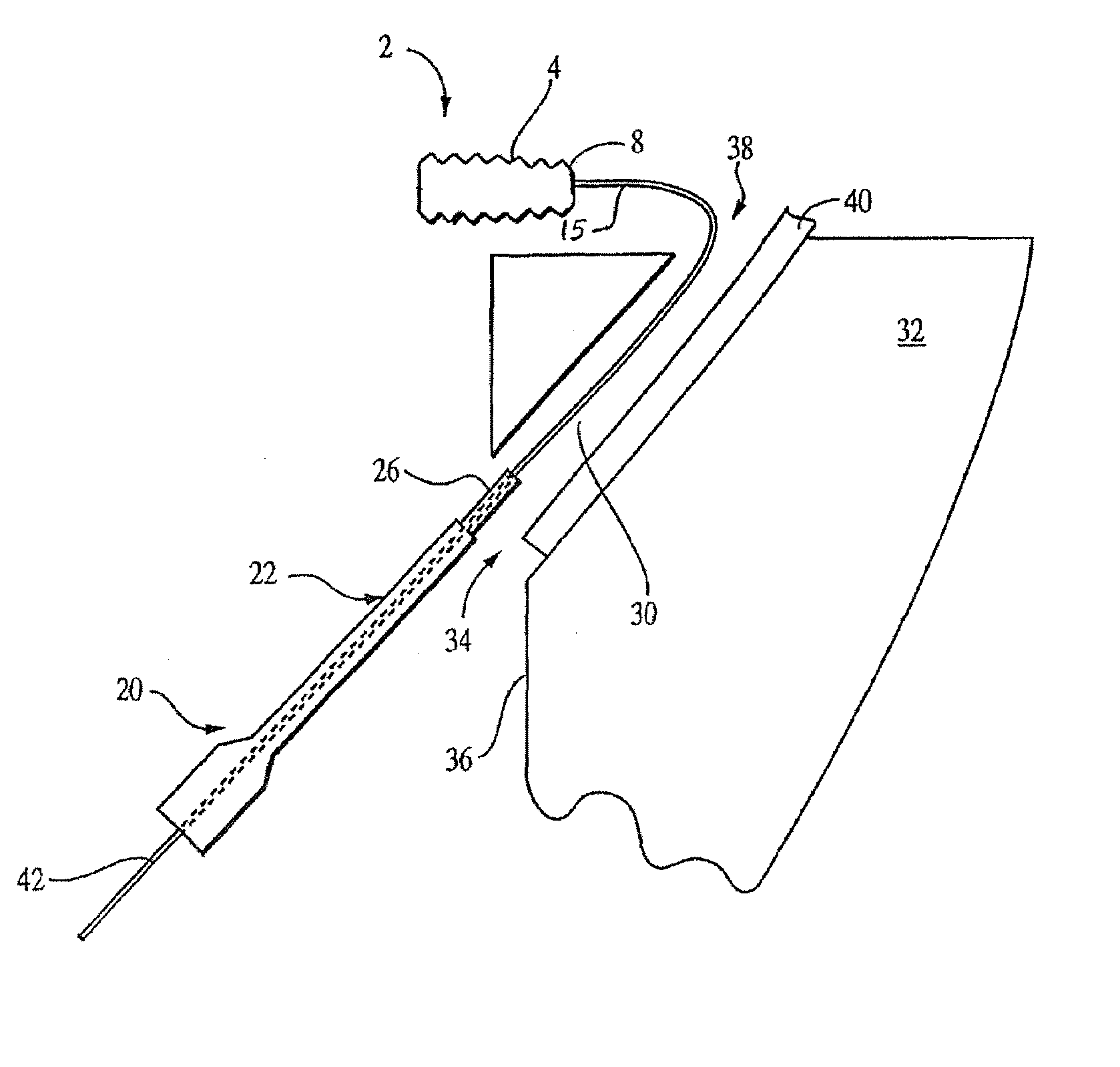
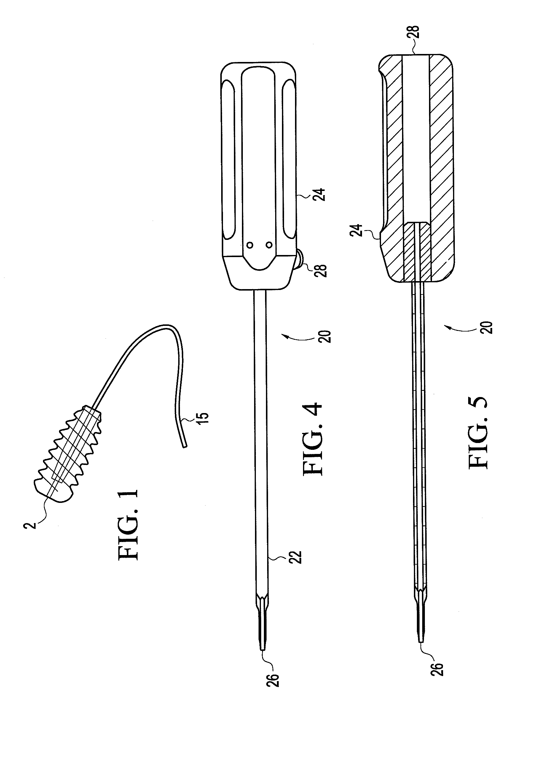
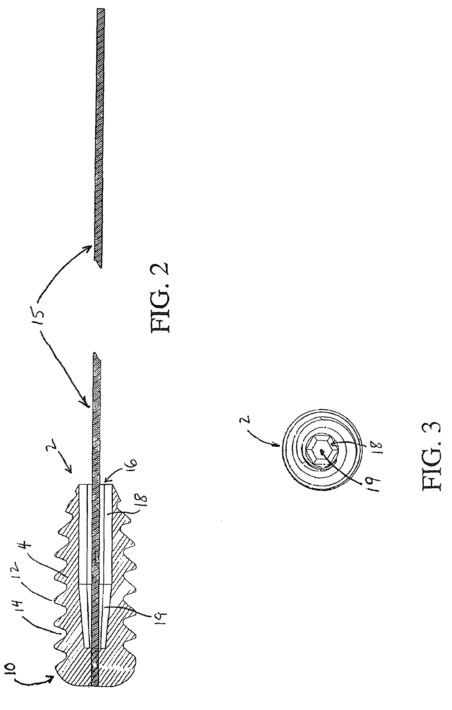
[0022]Referring initially to FIGS. 1-3, a bioabsorbable interference screw 2 for tenodesis of an anterior cruciate ligament graft is shown. Body 4 of the screw 2 features a continuous thread 6 provided substantially along the length of the body from a blunt front end 8 to a rounded back end 10. The thread preferably has flattened crests 12 and flattened troughs 14 to obviate ligament graft damage by the screw threads and enhance graft fixation. A length of suture 15 is insert-molded into interference screw 2 in a manner similar to that described in U.S. Pat. No. 5,964,783 and U.S. Patent Application Publ. No. 2003 / 0004545 A1, the disclosures of which are herein incorporated by reference. The suture may be a conventional surgical suture or an ultrastrong surgical suture, e.g., Fiber Wire suture, sold by Arthrex, Inc. of Naples, Fla., the assignee of the present application. Fiber Wire suture is formed of ultrahigh molecular weight polyethylene and is described in U.S. Ser. No. 09 / 950...
PUM
Abstract
Endosteal fixation of a ligament graft with a bioabsorbable interference screw installed in a retrograde manner in ACL reconstruction. The bioabsorbable interference screw is insert-molded with a length of suture extending from the distal tip of the screw for pulling the interference screw into the joint and into position for retrograde insertion at the top of the tibial tunnel. The interference screw has a cannulation extending partially through the screw from the leading tip. The cannulation is shaped to receive a correspondingly shaped driver. The driver is inserted into the tibial tunnel to engage the screw. By turning the driver, the interference screw is turned into the tibial tunnel in a retrograde manner. Accordingly, interference fixation of the graft near the tibial plateau is provided, thereby eliminating graft abrasion at the tibial plateau tunnel opening.
Description
[0001]This is a continuation-in-part of U.S. application Ser. No. 10 / 256,076, filed Sep. 27, 2002, now U.S. Pat. No. 7,063,717, which is a continuation-in-part of U.S. application Ser. No. 09 / 864,258, filed May 25, 2001, now U.S. Pat. No. 6,461,373, and claims the benefit of U.S. Provisional Application Ser. No. 60 / 207,235, filed May 26, 2000.FIELD OF THE INVENTION[0002]The present invention relates to interference screw fixation of replacement ligament grafts, and more particularly to methods and apparatus for retrograde placement and installation of an interference screw for graft fixation in a bone tunnel.BACKGROUND OF THE INVENTION[0003]Methods of anterior cruciate ligament (ACL) reconstruction using interference screw fixation are described in U.S. Pat. Nos. 5,211,647 and 5,320,626, the entire disclosures of which are incorporated herein by reference. In general, these methods of tenodesis involve drilling a tunnel through the tibia, drilling a closed tunnel (socket) into the f...
Claims
Application Information
Patent Timeline
Application Date:The date an application was filed.
Publication Date:The date a patent or application was officially published.
First Publication Date:The earliest publication date of a patent with the same application number.
Issue Date:Publication date of the patent grant document.
PCT Entry Date:The Entry date of PCT National Phase.
Estimated Expiry Date:The statutory expiry date of a patent right according to the Patent Law, and it is the longest term of protection that the patent right can achieve without the termination of the patent right due to other reasons(Term extension factor has been taken into account ).
Invalid Date:Actual expiry date is based on effective date or publication date of legal transaction data of invalid patent.
Patent Type & Authority Patents(United States)
IPC IPC(8): A61B17/04A61B17/88A61F2/08
CPCA61B17/8875A61F2/0805A61F2/0811
Inventor MORGAN, CRAIG D.WYMAN, JEFFREYSCHMIEDING, REINHOLDO'QUINN, PHILIP S.