Laminated bus bar assembly

a technology of bus bars and assembly parts, applied in the field of bus bars, can solve the problems of partial discharge, electrical failure, and partial discharge of the assembly of the laminated bus bars, and achieve the effects of reducing the number of parts

Inactive Publication Date: 2009-07-07
WORLD PROPERTIES
View PDF61 Cites 45 Cited by
  • Summary
  • Abstract
  • Description
  • Claims
  • Application Information

AI Technical Summary

Problems solved by technology

Partial discharges as well as electrical failures can occur during the use of laminated bus bar assemblies.
For example, exposing the laminated bus bar assembly to excessive vibration or heat changes can cause delamination to occur between layers.
Delamination is undesirable and can lead to creepage effects, which in turn can cause partial discharges.
Electrical failures and partial discharges are not desired in laminated bus bar assemblies.

Method used


Image

  • Laminated bus bar assembly
  • Laminated bus bar assembly
  • Laminated bus bar assembly

Examples


Embodiment Construction

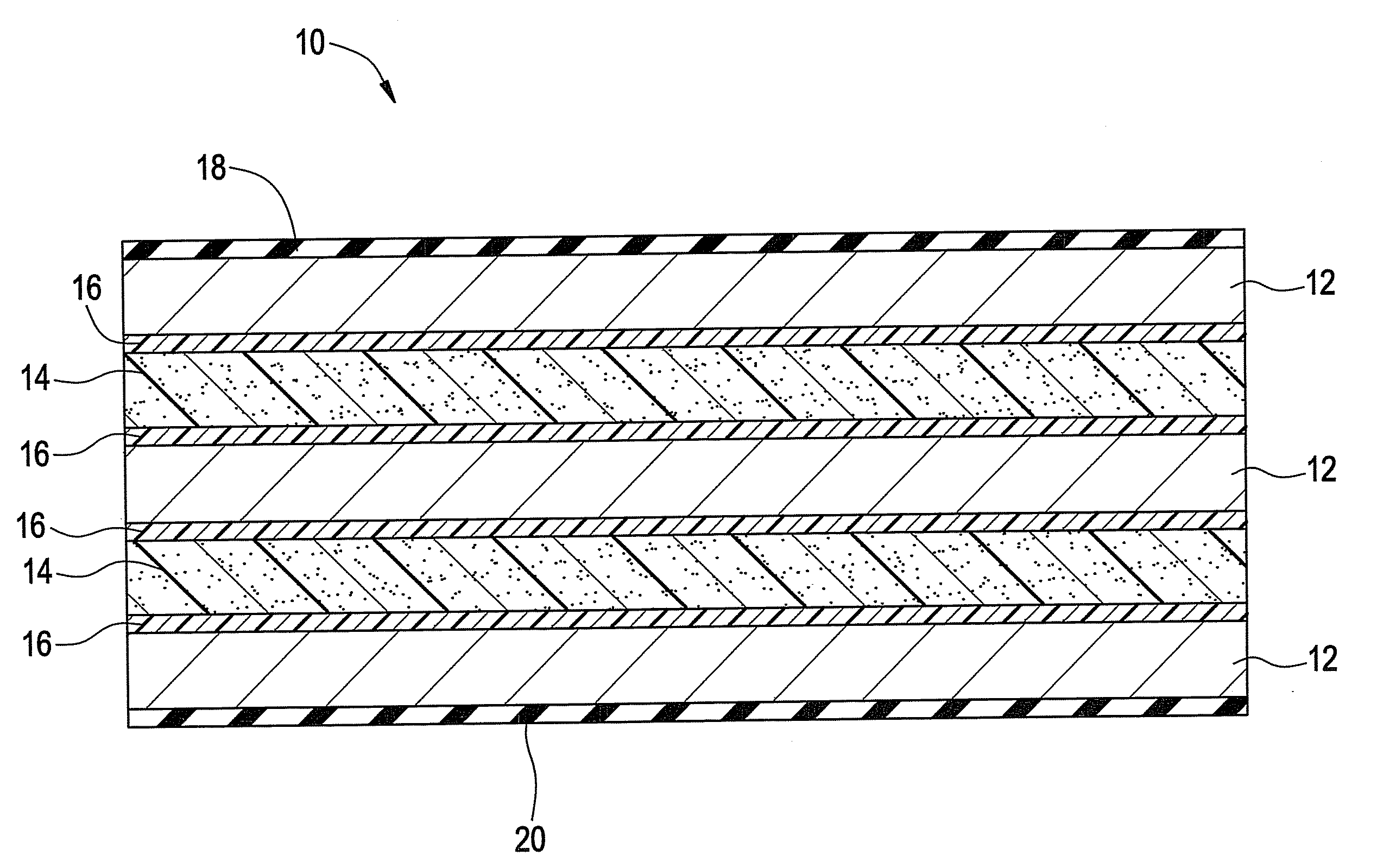
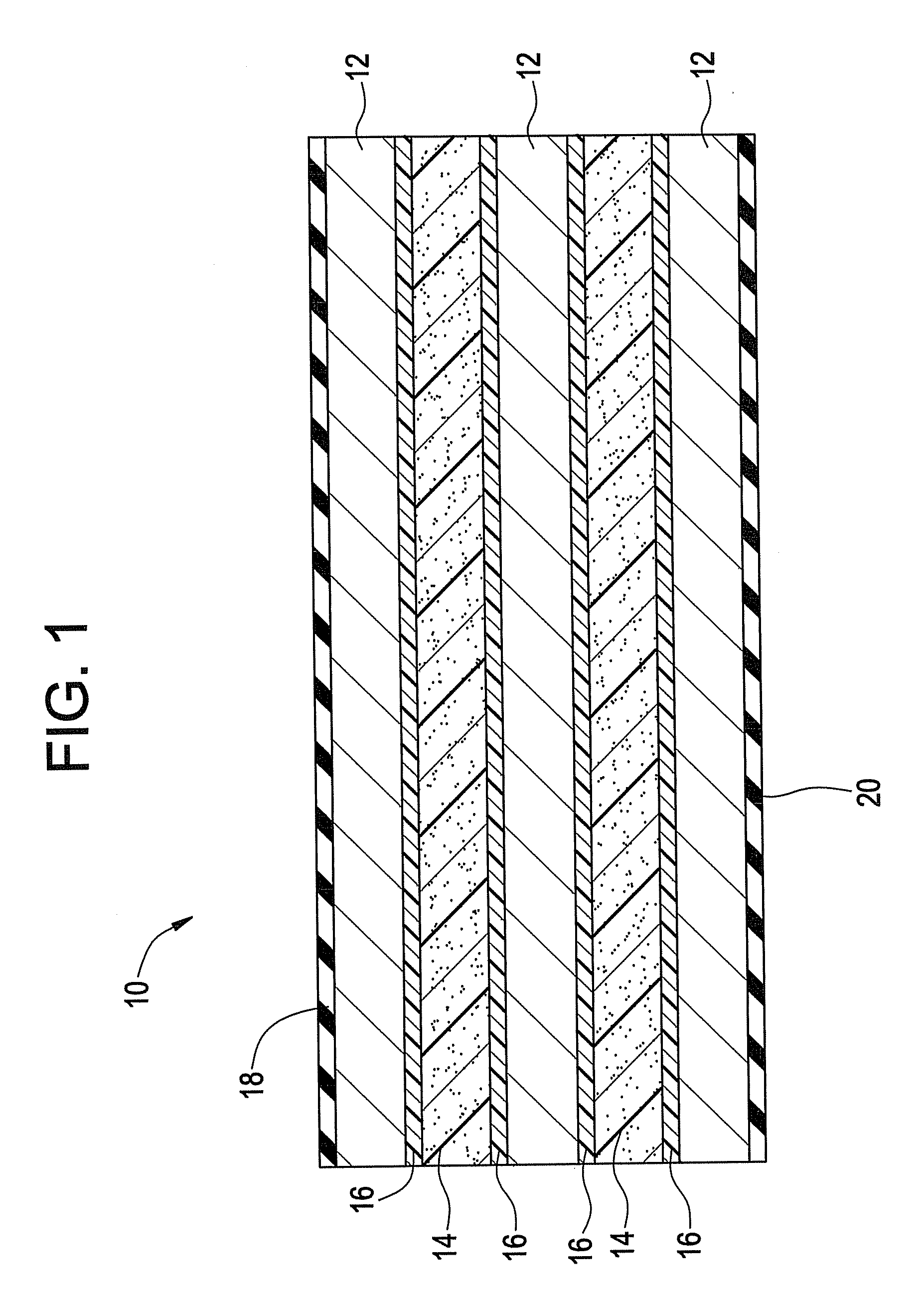
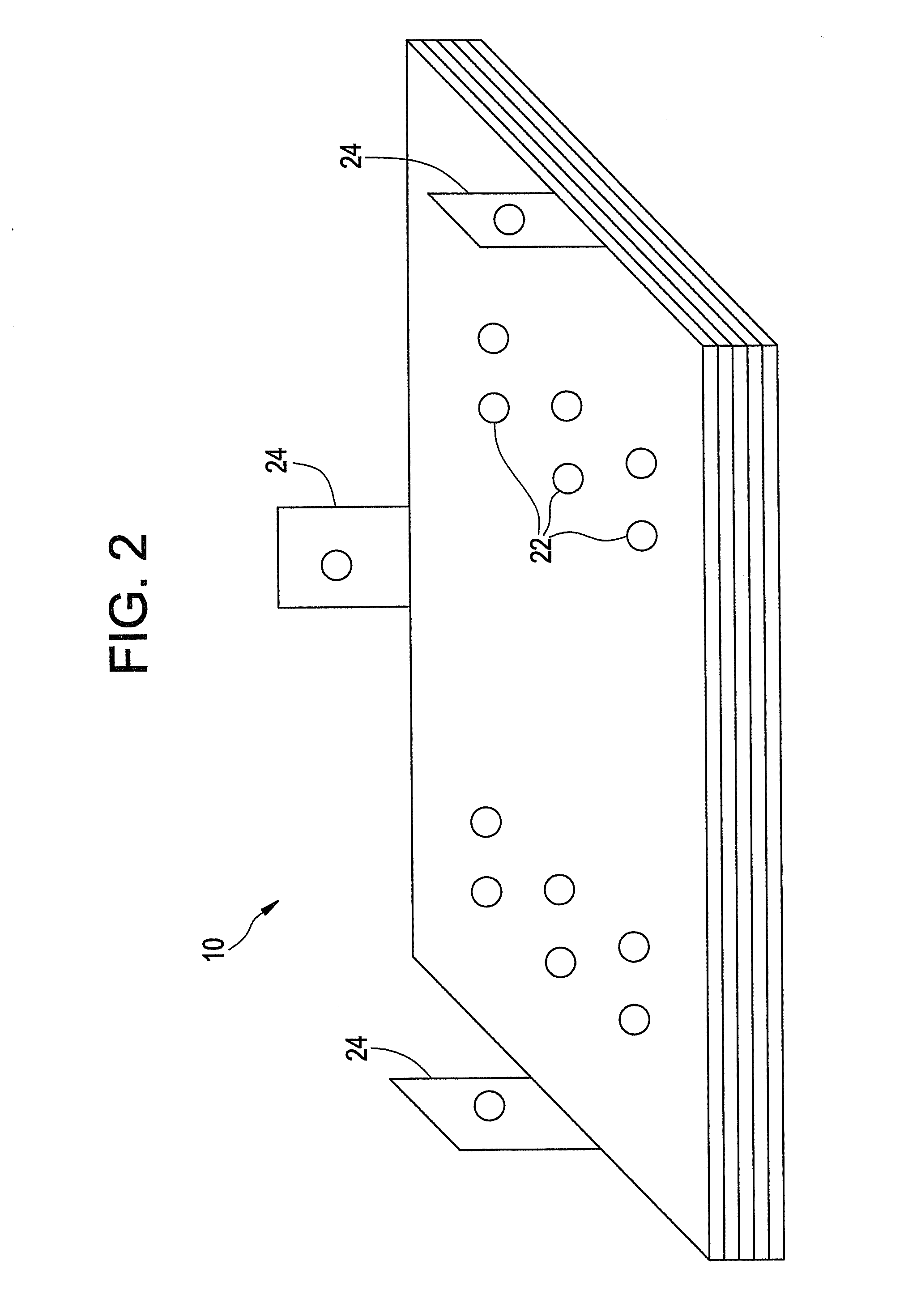
[0012]Disclosed herein is a bus bar assembly of laminar construction useful for power distribution systems, high power transistor modules, and the like. Referring now to FIGS. 1 and 2, a laminated bus bar assembly is shown generally designated by reference numeral 10. The laminated bus bar assembly 10 is exemplary only and is not intended to be limited to any particular shape, size, configuration, number of lamina, or the like. The laminated bus bar assembly 10 generally comprises alternating layers of a conductive sheet 12 and a foam dielectric sheet 14. Preferably, the conductive sheet 12 and a foam dielectric sheet 14 are sandwiched between non-conductive outer covers 18 and 20. Also shown are optional insulating layers 16 disposed between the conductive sheet 12 and the foam dielectric sheet 14. The non-conductive outer covers 18, 20 and insulating layers 16 are also referred to as insulating foils and may be fabricated from the same or different insulative materials. As shown m...


PUM


Abstract

A laminated bus bar assembly comprises alternating layers of a conductive layer and a foam dielectric layer. The foam dielectric layer has a dielectric constant greater than a solid non-porous dielectric constant of the same material, the use of which increases the partial discharge inception and extinction voltage levels, provides vibration resistance, decreases inductance and the like. The bus bar assembly of laminar construction is useful for power distribution systems, high power transistor modules, and the like.

Description

BACKGROUND[0001]The present disclosure relates to a bus bar assembly and more particularly, to a laminated bus bar assembly.[0002]Laminated bus bars of the type hereinafter described are used extensively in electronic devices where it is desirable to distribute power and ground to numerous points. The laminated bus bars generally exhibit high capacitance and low inductance. Typically these bars comprise one or more elongated, flat conductors, each having a plurality of spaced, integral lugs or terminals projecting from one or both longitudinal edges thereof. The conductors are laminated between layers of dielectric insulating material, the marginal edges of which project slightly beyond, and are sealed around the outer edges of the conductors. The conductors usually are similar in configuration, although in many instances the terminals on adjacent conductors are spaced differently so as to be laterally offset from each other in the assembly, thereby minimizing the possibility of acc...

Claims


Application Information

Patent Timeline
Patent Type & Authority Patents(United States)
IPC IPC(8): H02G3/04H02G5/00
CPCH02G5/005H05K7/14329
Inventor VANHOUTTE, CARLROELANDT, JEAN-PIERRE
Owner WORLD PROPERTIES
Why Eureka
Try Eureka