Vibrator module

a technology of vibrator module and crystal strip, which is applied in piezoelectric/electrostrictive/magnetostrictive devices, piezoelectric/electrostriction/magnetostriction machines, etc., can solve the problems of increasing the bonding cost of the crystal strip serving as a vibrator to the package, high bounding cost, and increased cost reduction and size, so as to achieve compact and inexpensive vibrator modules, stable vibration, and reduced vibration leakage from the vibr

Active Publication Date: 2009-07-07
MURATA MFG CO LTD
View PDF9 Cites 33 Cited by
  • Summary
  • Abstract
  • Description
  • Claims
  • Application Information

AI Technical Summary

Benefits of technology

[0011]Accordingly, it is an object of the present invention to provide a vibrator module in which a vibrator does not need to be bonded to a package and which is compact and inexpensive.
[0013]Since the vibrator unit, which is formed of a piezoelectric ceramic and includes the electrode, and the frame are formed as one piece, the frame with the vibrator can be used as a package in which a vibrator is formed in advance. Accordingly, no process of bonding a vibrator to a package is necessary. Additionally, since the IC is mounted in the frame with the vibrator, the vibrator module in which the vibrator and the IC are accommodated in one package can be obtained. In this case, since the hollow portion is formed between the vibrator unit and the IC, a region in which the vibrator unit can vibrate can be ensured.
[0014]Since the vibrator unit is formed of a piezoelectric ceramic, a region in which the vibrator is confined can be formed by molding to determine the size and form of the region. Additionally, a polarization region of the vibrator unit can be freely set.
[0021]According to the present invention, the vibrator module can be obtained, in which the vibrator unit and the frame are formed as one piece, and in which an individual vibrator does not need to be bonded to a package. In other words, the frame with the vibrator, in which the vibrator unit and the frame are formed as one piece, is used as a package, and the IC is mounted in the frame with the vibrator, whereby the compact and inexpensive vibrator module can be obtained.
[0022]Because the region in which the vibrator is confined can be formed by molding to determine the size and form of the region, vibration leakage from the vibrator unit can be reduced, and stable vibration can be obtained. Additionally, because the polarization region of the vibrator unit can be freely set, the electromechanical coefficient can be adjusted by changing the polarization region. Accordingly, different performances can be obtained even when vibrator units are formed of the same material.
[0023]Particularly, when a plate vertically vibrates in the thickness direction, a region in which the plate can vibrate needs to have a length more than or equal to ten times the thickness of the plate. For this reason, there was a problem that the shape of low-frequency (1 MHz to 20 MHz) vibrations having a large thickness becomes large. Accordingly, for example, in a case of crystal vibrators or the like, a process needed to be added, in which barrel polishing or the like was performed so that the periphery could be made thinner for size reduction. However, according to the present invention, the size of vibrators can be easily reduced using a mold, thereby contributing to the size reduction of low-frequency vibrators.

Problems solved by technology

However, because the IC 3, the crystal strip 4, the cover 5, and so forth need to be bonded to the package 2, the bounding cost becomes high.
Additionally, because the package structure becomes complicated, that is not preferable to cost reduction and size reduction.
However, even in a case of the vibrator module shown in FIG. 19, a problem that bonding cost for bonding the crystal strip serving as a vibrator to the package is increased has not been solved.
Additionally, because of the configuration in which the crystal strip and the IC are bounded to the package, there is also a problem that the cost of the package is relatively increased.
However, recently, designs capable of reducing the cost of vibrators have been advanced, resulting in a decrease in the size of vibrators.
In such a case, in the cost of vibrator modules, the cost of precision packages tends to be relatively increased, which is different from a case of large size products manufactured when vibrators and ICs were expensive.
Moreover, a problem with a space in which each vibrator is bonded to a package using an adhesive has to be also dealt with in order to reduce the size of vibrators.

Method used


Image

  • Vibrator module
  • Vibrator module
  • Vibrator module

Examples


Embodiment Construction

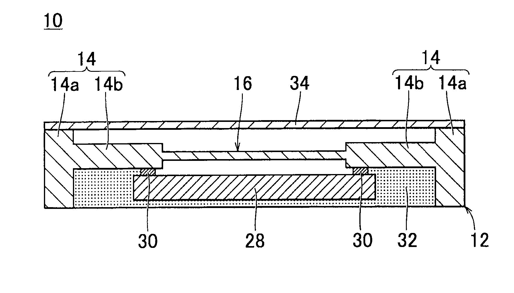
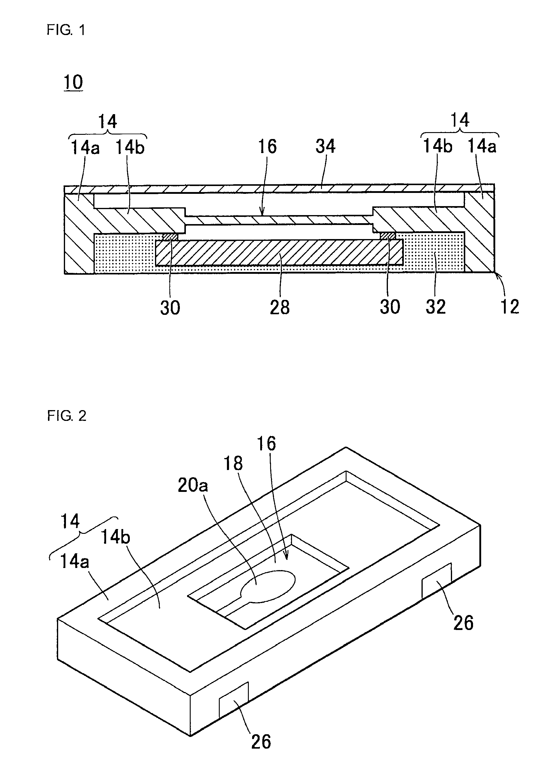
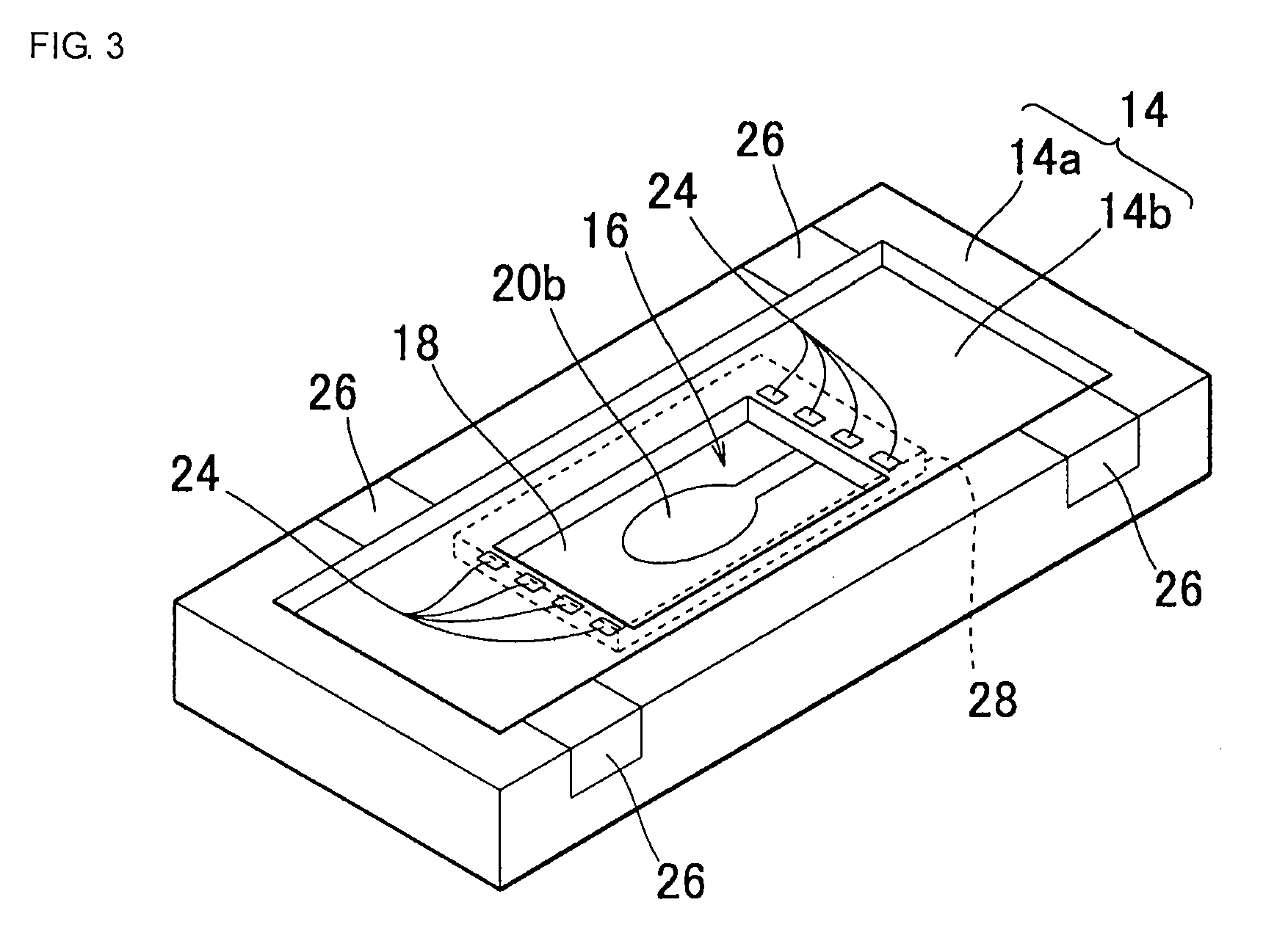
[0058]FIG. 1 is a cross-sectional view of a vibrator module according to the present invention, showing the vibrator module as an example. A vibrator module 10 includes a frame 12 with a vibrator. The frame 12 with the vibrator includes a frame 14, for example, in the shape of a rectangle as shown in FIGS. 2 and 3. The frame 14 includes an outer frame 14a in the shape of a square ring. Additionally, an inner frame 14b in the shape of a square ring is formed inside the outer frame 14a. The inner frame 14b is thinner than the outer frame 14a, and steps between the inner frame 14b and the outer frame 14a are formed on both surfaces of the inner frame 14b. Accordingly, the inner frame 14b is formed in portions more recessed than the outer frame 14a on both surfaces of the inner frame 14b. The outer frame 14a and the inner frame 14b are formed of, for example a piezoelectric ceramic.

[0059]In the central portion of the inner frame 14b, a vibrator unit 16 in the shape of a square plate is ...


PUM


Abstract

A vibrator module includes a frame having an outer frame and an inner frame. A vibrator unit is formed inside the inner frame. The frame and the vibrator unit are formed of a piezoelectric ceramic or the like as one piece. On one side of the vibrator unit, an IC is mounted so that a hollow portion is provided between the vibrator unit and the IC. The periphery of the IC is filled with a resin material. On the other side of the vibrator unit, a top cover serving as a sealing material is mounted so that a hollow portion is provided between the vibrator unit and the top cover.

Description

CROSS REFERENCE TO RELATED APPLICATIONS[0001]The present application is a continuation of International Application No. PCT / JP2007 / 050938, filed Jan. 23, 2007, which claims priority to Japanese Patent Application No. JP2006-034269, filed Feb. 10, 2006, the entire contents of each of these applications being incorporated herein by reference in their entirety.FIELD OF THE INVENTION[0002]The present invention relates to vibrator modules. More particularly, the present invention relates to a vibrator module, such as an oscillation module, a time module, or a sensor module, in which a piezoelectric vibrator and an IC are used in combination.BACKGROUND OF THE INVENTION[0003]As a vibrator module in which a piezoelectric vibrator and an IC are used in combination, for example, an oscillation module that oscillates a piezoelectric vibrator at a resonance point to output a clock, a time module, a voltage-controlled oscillator (VCO), a TCXO module in which an EEPROM or the like is mounted and ...

Claims


Application Information

Patent Timeline
Patent Type & Authority Patents(United States)
IPC IPC(8): H01L41/053
CPCH03H9/0595H03H9/0547
Inventor FUJIMOTO, KATSUMI
Owner MURATA MFG CO LTD
Why Eureka
Try Eureka