Cyclically liquid feeding apparatus

A liquid circulation and supply device technology, applied in cooling fluid circulation devices, household refrigeration devices, liquid level control, etc., can solve the problems of unbalance, large liquid level fluctuations, and high prices, and achieve easy temperature adjustment and elimination of liquid level. The effect of change, cheap installation

Active Publication Date: 2012-10-17
SMC CORP
View PDF7 Cites 5 Cited by
  • Summary
  • Abstract
  • Description
  • Claims
  • Application Information

AI Technical Summary

Problems solved by technology

[0004] However, in the above-mentioned conventional example, since the high-temperature container and the low-temperature container are separately installed at separate positions, not only the wide installation space is dedicated to the two containers, but the size of the device must be increased. Exothermic adiabatic processing complicates the structure and increases the price
[0005] In addition, when the liquid is supplied from the above two containers to the load, the liquid moves between the two containers with the switching operation of the above mixing unit, and the liquid levels of the liquids in the two containers fluctuate greatly to become unbalanced. state, which is easy to cause obstacles to the temperature adjustment of the liquid in each container
Therefore, in Patent Document 3, a water storage tank is provided to absorb the increase and decrease of liquid in the cooling side (low temperature) container and the heating side (high temperature) container, but not only the installation space of the water storage tank is increased, but also if the temperature is not managed The liquid in the storage tank flows into the above-mentioned cooling side container and heating side container, then the temperature adjustment of the liquid in the two containers also becomes more difficult.

Method used


Image

  • Cyclically liquid feeding apparatus
  • Cyclically liquid feeding apparatus

Examples


Embodiment Construction

[0021] Preferred Mode for Carrying Out the Invention

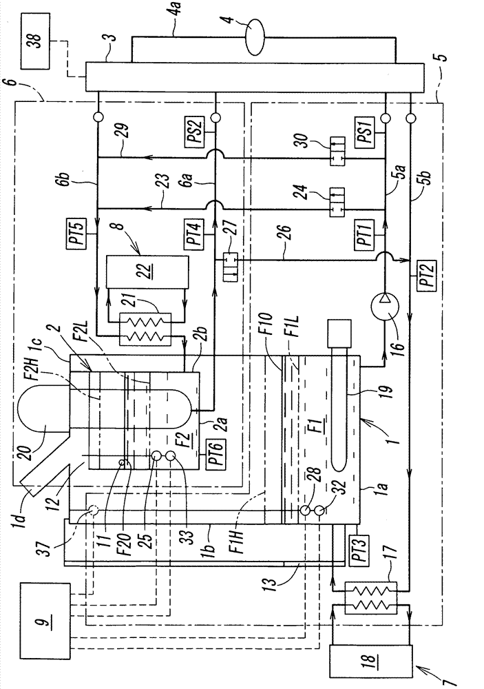
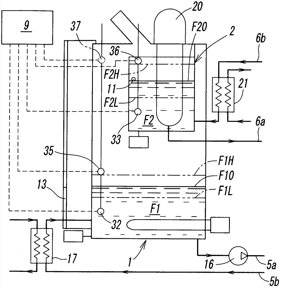
[0022] figure 1 A configuration diagram showing a first embodiment of the liquid circulation supply device according to the present invention. This liquid circulation supply device has a large-capacity outer container 1, a small-capacity inner container 2, a valve device 3, a liquid circulation path 5 for the outer container, a liquid circulation path 6 for the inner container, a first temperature adjustment device 7, a second The temperature adjusting device 8 and the control device 9, the above-mentioned large-capacity external container 1 accommodates the first liquid F1, and the above-mentioned small-capacity internal container 2 is installed inside the external container 1, and contains a second fluid having a temperature different from that of the above-mentioned first liquid F1. Two liquids F2, the valve device 3 supplies the first liquid F1 and the second liquid F2 individually or mixed to the load 4, and the liqu...


PUM


Abstract

The invention provides a cyclically liquid feeding apparatus. An outer tank and an inner tank having liquid at different temperatures, and a load are connected to each other via outer and inner tank liquid circulating channels and a valve unit. A first opening-and-closing valve is connected to a first bypass flow-channel connecting an outer tank feed channel and an inner tank feedback channel, a second opening-and-closing valve is connected to a second bypass flow channel connecting an inner tank feed channel and an outer tank feedback channel to detect the liquid level of the liquid in the outer tank and the liquid level of the liquid in the inner tank by a liquid level sensor. The liquid levels are adjusted by selectively opening the first opening-and-closing valve and the second opening-and-closing valve when the liquid levels in both tanks become uneven in the process of cyclically feeding the liquid from the tanks to the load.

Description

technical field [0001] The present invention relates to a liquid circulation supply device for cooling a load by circulatingly supplying a cooling liquid to the load. More specifically, it relates to a liquid circulation supply device for cooling a load using two liquids having different liquid temperatures. Background technique [0002] For example, in various manufacturing devices such as semiconductor manufacturing devices and liquid crystal manufacturing devices, in order to cool the device (load) that generates heat and keep the temperature constant, cooling liquid is circulated from a liquid circulation supply device to cool the load. In this case, as disclosed in the following Patent Documents 1-3, in order to perform high-precision temperature control according to the amount of heat of the load, it may be necessary to prepare two types of liquids with different liquid temperatures. , through a mixing assembly composed of a plurality of three-way valves, etc., the liq...

Claims


Application Information

Patent Timeline
Patent Type & Authority Applications(China)
IPC IPC(8): G12B15/02
CPCG05D9/12G05D23/1393F25D17/02F25D9/00H01L21/02F25D29/00
Inventor 坂口哲郎
Owner SMC CORP
Why Eureka
Try Eureka