Filtering flow box for mounting to a silo

a filter flow box and silo technology, applied in the direction of solid separation, domestic stoves or ranges, lighting and heating apparatus, etc., can solve the problems of increasing clogging of filter apertures, forming so-called angel hair, and causing a lot of clogging of apertures, so as to achieve convenient removal, cleaning, and replacement without creating a mess or a hazard

Inactive Publication Date: 2009-10-15
ALLEY INDS
View PDF16 Cites 4 Cited by
  • Summary
  • Abstract
  • Description
  • Claims
  • Application Information

AI Technical Summary

Benefits of technology

[0011]It is a first purpose of the present invention to provide a filtering flow box having a fi

Problems solved by technology

One problem associated with plastic pellets is the formation of so-called “angel hair.” Angel hair is thin, elongated plastic strands that result from the unraveling of plastic pellets.
Angel hair is generally undesirable because they are not useful for processing, and therefore must be removed from a supply of pellets before use.
Over time, as angel hair accumulates on the upstream surface of the filter, the apertures of the filter become increasingly clogged and the throughput of pellets steadily decreases.
A problem that is commonly associat

Method used


Image

  • Filtering flow box for mounting to a silo
  • Filtering flow box for mounting to a silo
  • Filtering flow box for mounting to a silo

Examples


Embodiment Construction

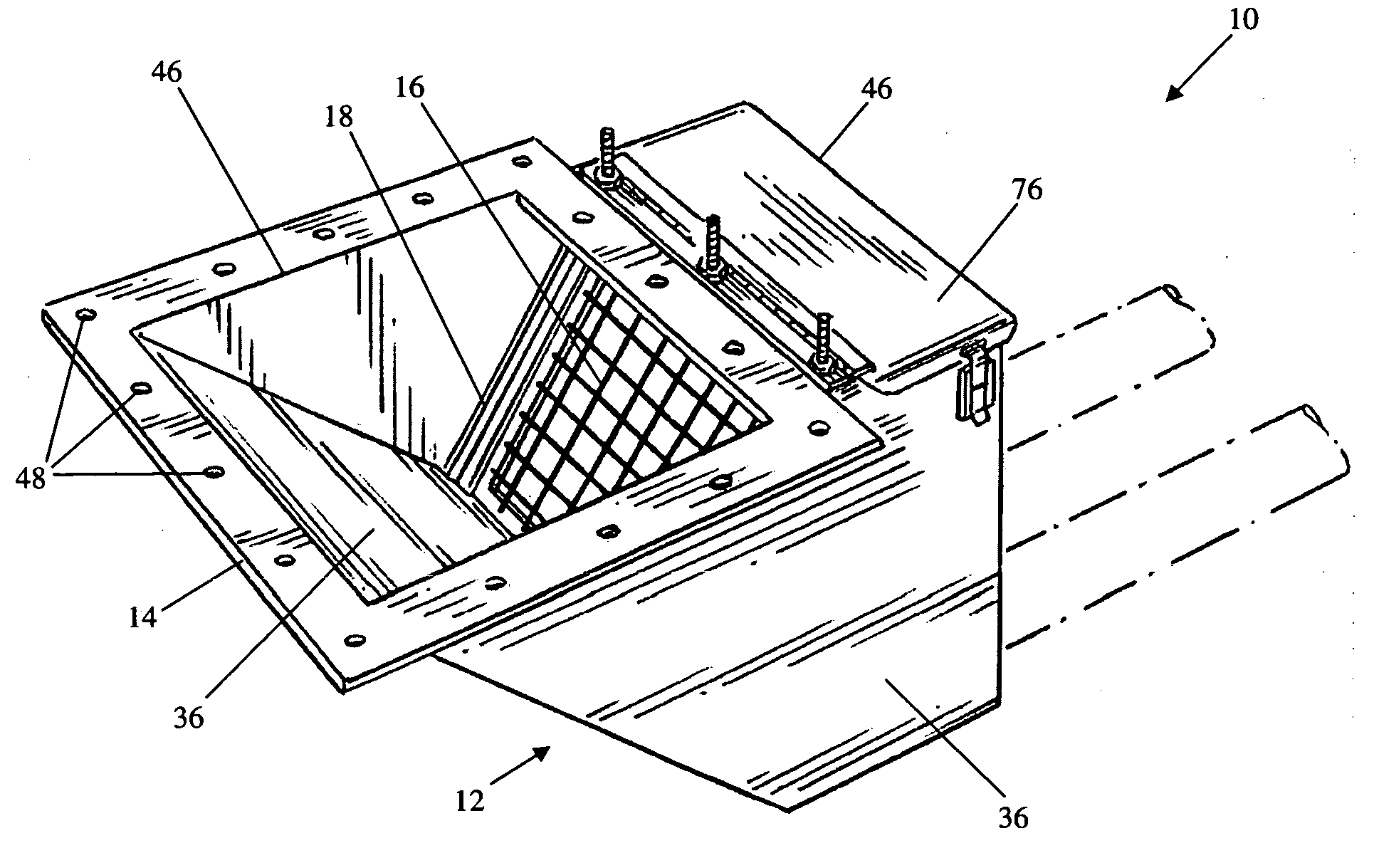
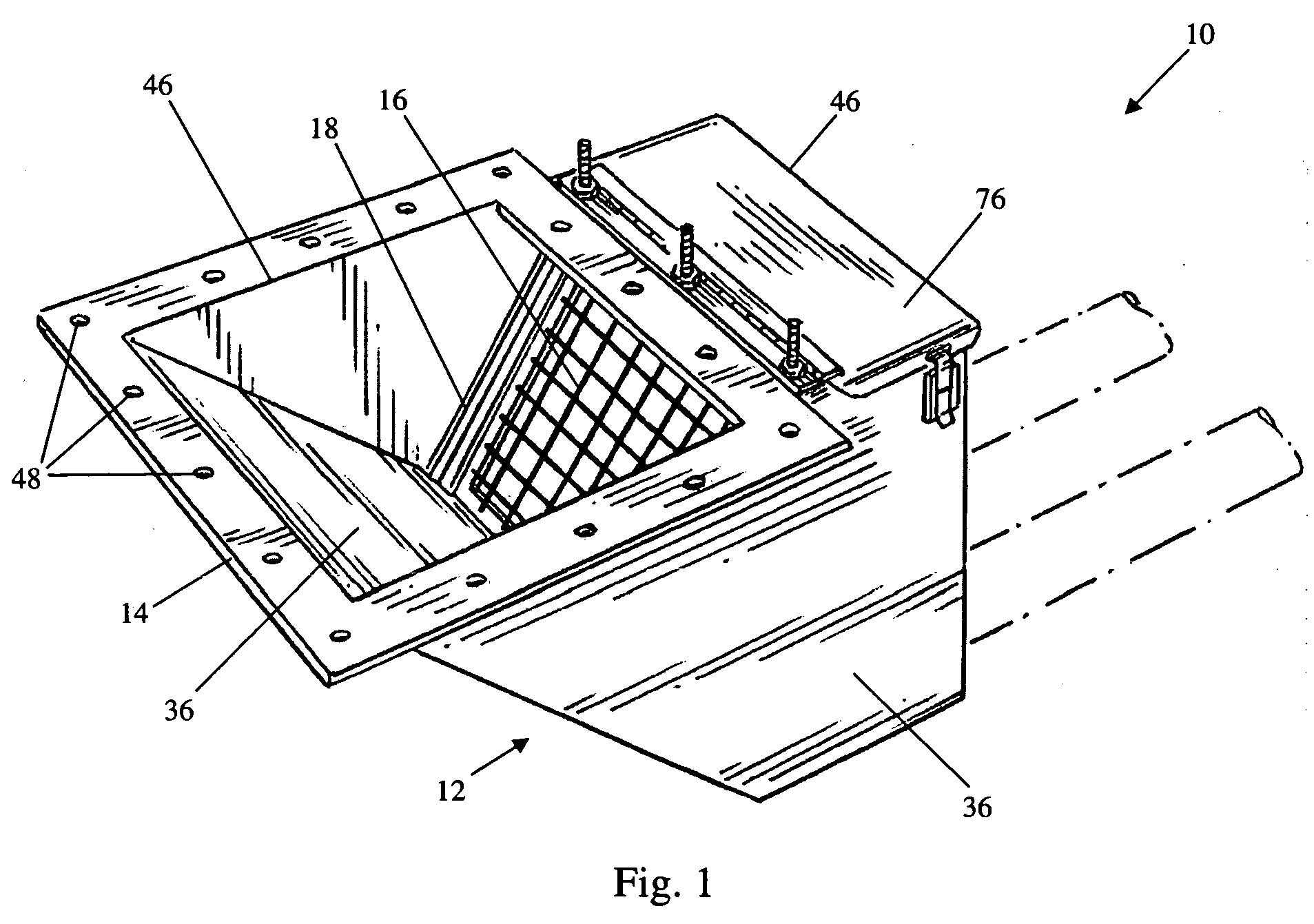
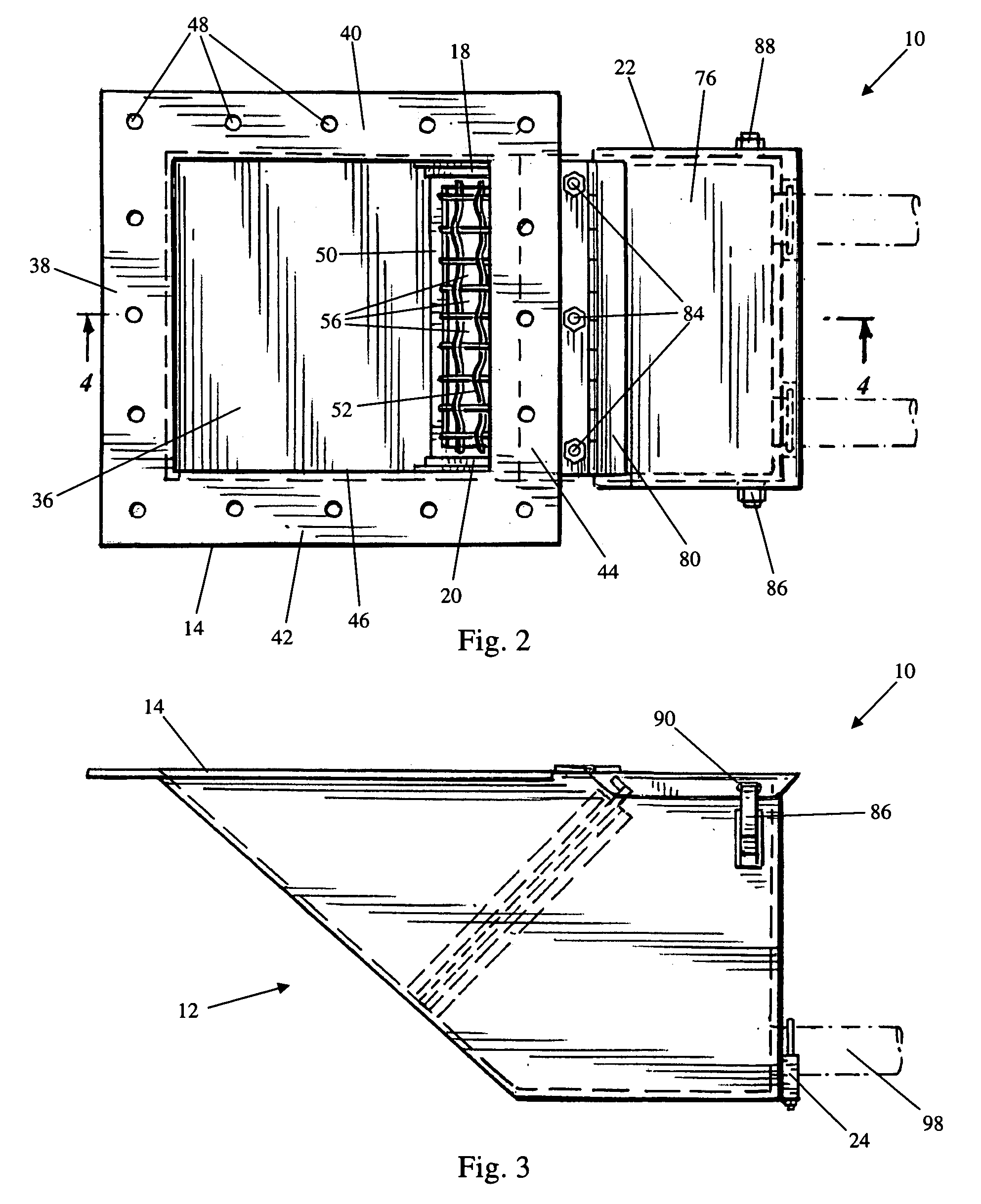
[0027]Referring to FIGS. 1-4 and 8, the filtering flow box 10 has a main housing 12, a mounting flange 14, a removable filter 16, two filter guides 18 and 20, a filter cover assembly 22, and two feed-line clamps 24 and 26. All components of the box 10 are formed of stainless steel unless otherwise noted, although all other materials that are sufficiently rigid and durable, such as aluminum, iron, and various plastics and composites, are contemplated as will be understood by the person having ordinary skill. For the sake of convenience and clarity, terms such as “front,”“rear,”“top,”“bottom,”“up,”“down,”“inwardly,”“outwardly,”“lateral,” and “longitudinal” will be used herein to describe the relative placement and orientation of various components of the invention, all with respect to the geometry and orientation of the filtering flow box 10 as it appears in FIG. 1 as mounted in an operable orientation. Said terminology will include the words specifically mentioned, derivatives thereo...


PUM

PropertyMeasurementUnit
Angleaaaaaaaaaa
Angleaaaaaaaaaa
Angleaaaaaaaaaa

Abstract

A filtering flow box for receiving a supply of plastic pellets from a bottom-unloading tower silo and removing undesirable plastic strands (“angel hair”) from the pellets before they are processed for manufacturing. The box has an angled entry wall for laterally channeling pellets to an angled filter. The pellets pass through the filter and angel hair collects on the filter's upstream surface. The filter can be removed from the box at an angle having a vertical component for cleaning, thus allowing any pellets that have accumulated on top of the filter to fall back into the box.

Description

(e) BACKGROUND OF THE INVENTION[0001]1. Field Of The Invention[0002]This invention relates generally to a filter for sifting and channeling material flowing out of a bottom-unloading tower silo, and relates more particularly to a filtering flow box for receiving plastic pellets flowing from a bottom-unloading tower silo, sifting unwanted plastic strands (“angel hair”) out of the supply of pellets, and channeling the sifted pellets into vacuum feed lines for further processing.[0003]2. Description Of The Related Art[0004]Plastic pellets comprise the raw material for many plastic articles of manufacture. Because of their small size and granular nature, such pellets are preferred for their ease of handling and processing. In order to convert plastic pellets into a form that is useable for fabrication, the pellets are melted down, and the resulting molten plastic is subsequently used in processes such as injection molding or blow molding.[0005]Typically, plastic pellets are stored in bo...

Claims


Application Information

Patent Timeline
IPC IPC(8): B07B1/46B07B1/04B07B13/14
CPCB07B1/04B07B2201/02B07B1/4681B07B1/46B29B7/60
Inventor BORGER, RONALD E.STEINBRUNNER, TROY
Owner ALLEY INDS
Why Eureka
Try Eureka