Connection assembly for formwork

a technology of connecting parts and formwork, applied in the direction of form/shuttering/falseworks, shaping building parts, construction, etc., can solve the problem of using additional tools, and achieve the effect of convenient removal and replacemen

Active Publication Date: 2021-04-13
PERI FORMWORK SYST INC
View PDF118 Cites 0 Cited by
  • Summary
  • Abstract
  • Description
  • Claims
  • Application Information

AI Technical Summary

Benefits of technology

[0003]The present application overcomes the disadvantages of the prior art by providing a connection assembly reduces the difficulty in removing a bolt from a formwork system and provides a removable bolt block assembly for conveniently removing and replacing bolt block assemblies having different parameters without requirement the user of additional specific formwork assemblies.

Problems solved by technology

This can be a difficult process or can require the use of additional tools and thus be inconvenient.
This can be inconvenient where various types of bolts are used on a site, thus requiring specific formwork assemblies to match.

Method used


Image

  • Connection assembly for formwork
  • Connection assembly for formwork
  • Connection assembly for formwork

Examples


Embodiment Construction

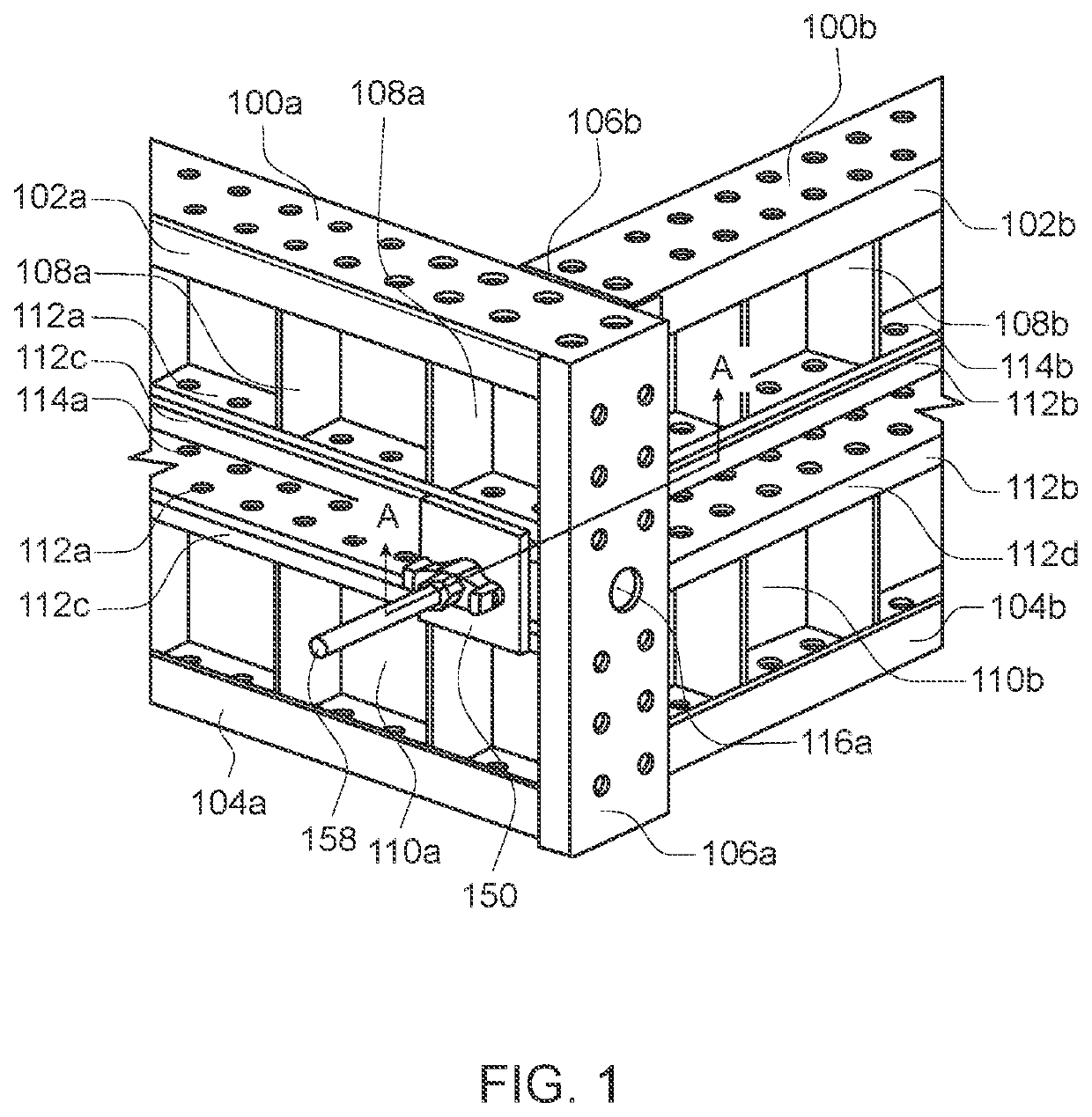
[0030]FIG. 1 is a partial perspective view of a plurality of formwork elements 100a, 100b connected via a connection assembly 150 according to one or more aspects of the disclosure.

[0031]The formwork element 100a can include a top rail 102a, a bottom rail 104a that opposes and is parallel or substantially parallel to the top rail 102a, a first side rail 106a, and a second side rail (not shown) that opposes and is parallel or substantially parallel to the first side rail 106a. The formwork element 100a can be of any size, shape or dimension in order to achieve the task of forming fresh concrete. For example, the formwork element 100a can be rectangular or substantially rectangular, with the top rail 102a and the bottom rail 104a having equal length and the first side rail 106a and the second side rail (not shown) having equal length.

[0032]The top rail 102a, the bottom rail 104a, and the side rail 106a can be formed of any type of metal, such as steel, steel alloy, aluminum, aluminum ...


PUM


Abstract

A connection assembly for formwork elements includes a counterplate, a bolt, and a bolt block. The counterplate can include a plurality of surfaces having differing heights that selectively engage with a waler during engagement or disengagement of the bolt from the formwork element. The formwork element can include a J-shaped waler that allows for easy climbing and / or hanging of objects on a site. The connection assembly can include a bolt block that removably engages a formwork element.

Description

FIELD OF THE INVENTION[0001]The present disclosure relates to connection assemblies for formwork.BACKGROUND OF THE INVENTION[0002]Certain formwork systems of the prior art use bolts to engage formwork elements with one another. During assembly and disassembly of the formwork system, the bolt may need to be removing or replaced depending on the circumstances. This can be a difficult process or can require the use of additional tools and thus be inconvenient. Such formwork systems may also have a fixed connection assembly that is specific to particular types of bolts. This can be inconvenient where various types of bolts are used on a site, thus requiring specific formwork assemblies to match.SUMMARY OF THE INVENTION[0003]The present application overcomes the disadvantages of the prior art by providing a connection assembly reduces the difficulty in removing a bolt from a formwork system and provides a removable bolt block assembly for conveniently removing and replacing bolt block as...

Claims


Application Information

Patent Timeline
Patent Type & Authority Patents(United States)
IPC IPC(8): E04G17/00F16B21/02E04G17/04F16B37/16
CPCE04G17/001E04G17/042E04G17/047F16B21/02F16B37/16E04G11/12E04G2009/028E04G9/06
Inventor JORGENSEN, DAVID L.HENNING, MARK D.
Owner PERI FORMWORK SYST INC
Why Eureka
Try Eureka