Electrode member, electron energy analyzer, photoelectron energy analyzer, and temperature measuring apparatus

a technology of electron energy analyzer and electron energy analyzer, which is applied in the direction of heat measurement, instrumentation, and beam deviation/focusing by electric/magnetic means, etc. it can solve the problem of unclear definition of measured physical value, inability to simultaneously multi-functional measurement with another surface analysis measurement, and inability to measure physical values. the effect of a single surface analysis measurement and a single electron energy spectrum

Inactive Publication Date: 2012-06-21
NAT INST OF ADVANCED IND SCI & TECH +1
View PDF3 Cites 4 Cited by
  • Summary
  • Abstract
  • Description
  • Claims
  • Application Information

AI Technical Summary

Benefits of technology

[0037]The electrode member according to the present invention has spherical surface parts constituting a portion of a spherical surface, and a plurality of spherical electrode parts having different radiuses of the spherical surface parts, so that the spherical electrode parts have the same spherical center point. In addition, the spherical electrode parts are arranged to be insulated from each other to independently apply voltages. Since electron passage openings are formed at positions crossing a plurality of straight lines of the spherical electrode parts radially extending from the center point to extract the electrons moving from the center point to the outside of the electrode in a straight line, appropriate voltages are applied to the spherical electrode parts so that electrostatic lenses for the electrons may be formed between the adjacent electrode parts.
[0038]In addition, the electrons emitted from the sample fly freely to pass through the opening of the innermost spherical electrode part, a flight trajectory of the electrons is controlled by the electrostatic lens, and finally, the electrons perpendicularly enter a center portion of the opening of the outermost spherical electrode part (retarding electrode). While the electrons having higher kinetic energy than the barrier potential formed at the outermost spherical electrode part can pass through the outermost spherical electrode part, the electrons having lower kinetic energy than the barrier potential cannot pass through the outermost spherical electrode part. Accordingly, only the electrons passing through the outermost spherical electrode part are counted by a detection part. Such electron intensity is recorded while scanning the retarding voltage applied to the outermost spherical electrode part, and thus, an integrated electron energy spectrum can be obtained. Further, as the obtained integrated electron energy spectrum is subjected to differential calculation, for example, in a computer, a desired electron spectrum can be obtained.
[0039]In addition, since the retarding electric field type is employed and the electrode member has a spherical shape, the photoelectrons emitted from the sample are detected within a range of a large solid angle, a maximum of 2π, and high sensitivity measurement can be realized in comparison with the conventional concentric hemispherical electrostatic analyzer.
[0040]Further, a voltage is applied to each of the spherical electrode part so that the electrostatic lens is configured between the openings of adjacent spherical electrode parts, controlling a trajectory of the photoelectrons emitted from the sample. Accordingly, the electrons entering the outermost spherical electrode part (retarding electrode) can converge at a center portion in which potential of the opening is uniform, and the electrons can perpendicularly enter the outermost spherical electrode part (retarding electrode). Therefore, high energy resolution not available in the related art can be realized.
[0041]Further, as an electron detector that can determine a position of electrons on the detector arriving at the detection part is used, the number of electrons can be counted at each emission angle of the electrons emitted from the sample. Accordingly, electron energy spectra of emission angles of the photoelectrons to a wide emission angle range can be simultaneously measured using the electron energy analyzer of the present invention, without scanning installation positions of the electron energy analyzer with respect to the samples.
[0042]According to the electron energy analyzer of the present invention, since the electrode member of the present invention is provided, a compact and inexpensive analyzer can be realized.

Problems solved by technology

However, the contact method is not an effective temperature measurement means with respect to a clean surface, a surface of a thin film in a thin film manufacturing process, or a sample controlled in an order of nanometers, since a sensor part of the thermocouple or the resistance thermometer is large and thermally contacts a measurement object.
In recent times, while local temperature measurement (SThM) has been attempted by installing a thermocouple or a resistance thermometer at an end of an AFM tip, definition of a measured physical value is unclear and simultaneous multi-functional measurement with another surface analysis measurement is impossible because of its complexity of measuring apparatus.
However, since an actual material is not an ideal blackbody radiation source, a thermal radiation amount from the surface of the material depends on thermo-optical properties (emissivity) of the surface.
Accordingly, if there is no detailed information on the emissivity of the material, the surface temperature of the measurement object cannot be precisely measured.
As described above, due to the above-mentioned reasons, there is no practical temperature measuring means that can satisfy the following measurement needs in surface analysis or nano-scientific measurement fields: (a) locality (surface selectivity), (b) non-contact and (c) simultaneous multi-functional measurement.

Method used


Image

  • Electrode member, electron energy analyzer, photoelectron energy analyzer, and temperature measuring apparatus
  • Electrode member, electron energy analyzer, photoelectron energy analyzer, and temperature measuring apparatus
  • Electrode member, electron energy analyzer, photoelectron energy analyzer, and temperature measuring apparatus

Examples


Embodiment Construction

[0054]Hereinafter, embodiments for implementing an electrode member, an electron energy analyzer, a photoelectron energy analyzer, and a temperature measuring apparatus in accordance with the present invention will be described.

[0055]In addition, the embodiment is specifically described so that the spirit of the present invention is better understood, but does not limit the invention unless the context clearly indicates otherwise.

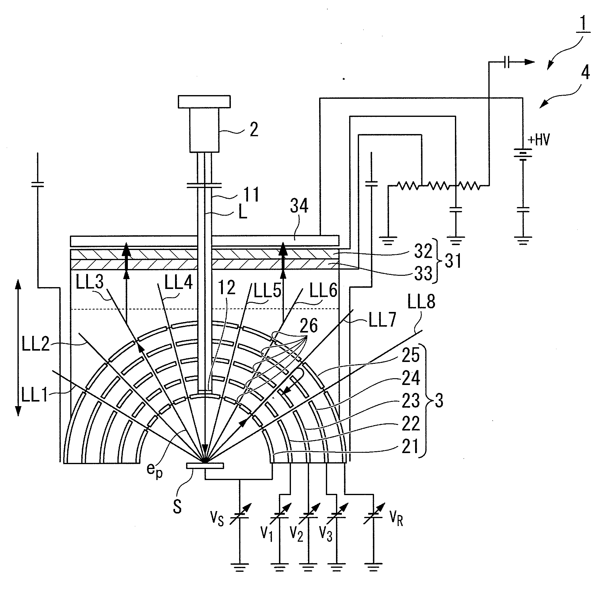
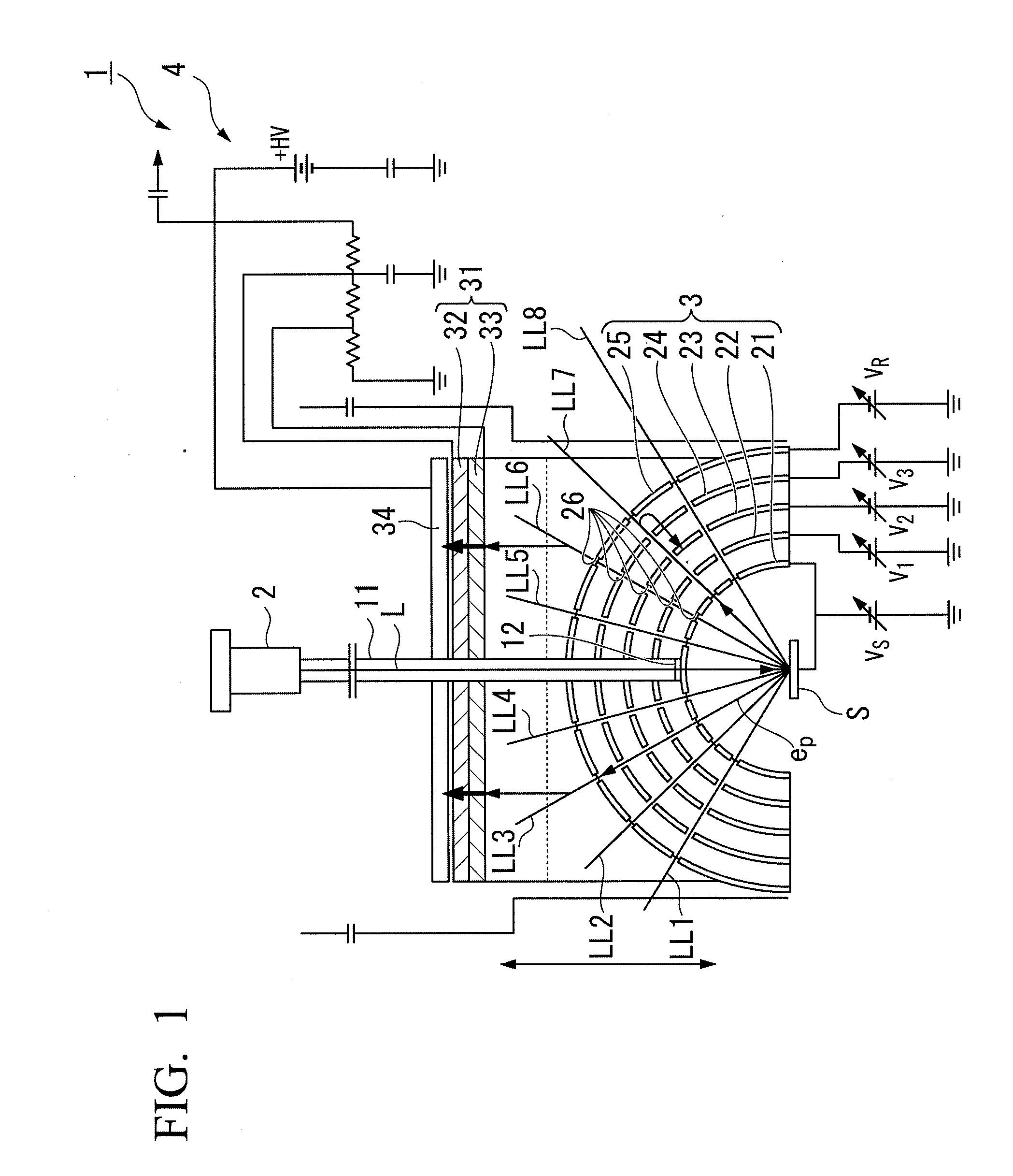
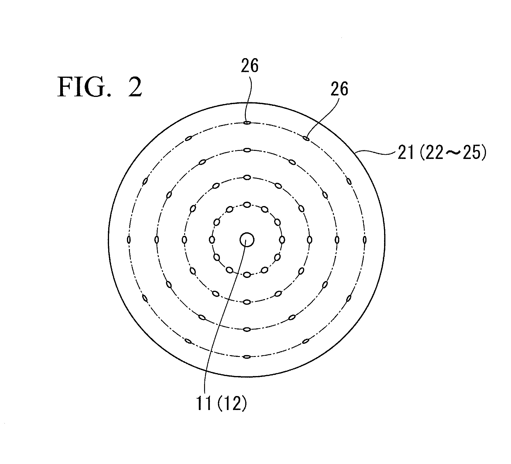
[0056]FIG. 1 is a cross-sectional view illustrating a photoelectron energy analyzer in accordance with a preferred embodiment of the present invention. FIG. 2 is a plan view illustrating a spherical electrode part of the photoelectron energy analyzer in accordance with a preferred embodiment of the present invention. A photoelectron energy analyzer 1 includes a light source 2 configured to irradiate light L to a sample S, an electrode (member) 3 through which photoelectrons ep excited by the light L and emitted from the sample S pass, and a detector 4 confi...


PUM

PropertyMeasurementUnit
energy resolutionaaaaaaaaaa
absolute temperaturesaaaaaaaaaa

Abstract

Disclosed is an electrode member which has spherical sections, each of which configures a part of a sphere, and a plurality of spherical electrode sections wherein the radiuses of the spherical sections are different from each other. The spherical electrode sections are disposed in a state wherein the center points of the respective spheres match each other and the spherical electrode sections are insulated from each other such that voltages can be independently applied thereto. Electron-passing openings for straightly taking out electrons, which are moving from the center point, to the outside of the electrode are formed at positions where the spherical electrode sections and a plurality of straight lines radially extending from the center point intersect each other.

Description

TECHNICAL FIELD[0001]The present invention relates to an electrode member, an electron energy analyzer, a photoelectron energy analyzer, and a temperature measuring apparatus, and more particularly, to an electron measuring technique in which highly sensitivity measurement is possible, high energy resolution is realized, an absolute temperature (a thermodynamic temperature) at a surface of a material such as a metal can be measured with high precision, a use as a standard thermometer for a surface temperature is possible, and a small size and a low price are realized.[0002]Priority is claimed on Japanese Patent Application No. 2009-197670, filed Aug. 28, 2009, the content of which is incorporated herein by reference.BACKGROUND ART[0003]In a related art, methods to measure sample temperature may be classified as contact method, which typically employs a thermocouple or a resistance thermometer, or as non-contact method, which typically employs an infrared radiation thermometer.[0004]...

Claims


Application Information

Patent Timeline
Patent Type & Authority Applications(United States)
IPC IPC(8): H01J47/00G01K11/00H01J3/18
CPCG01N23/227G01K11/30
Inventor ISHII, JUNTAROKINOSHITA, IKUO
Owner NAT INST OF ADVANCED IND SCI & TECH
Why Eureka
Try Eureka