Low loss NMR sample holder

a sample holder and low-loss technology, applied in the field of sample cells, can solve the problems of reducing the sensitivity of the nmr instrument, and inherently compromising the sensitivity of the sample volum

Inactive Publication Date: 2009-07-07
AGILENT TECH INC
View PDF13 Cites 8 Cited by
  • Summary
  • Abstract
  • Description
  • Claims
  • Application Information

AI Technical Summary

Benefits of technology

[0012]Another embodiment of the sample vessel assembly adds an auxiliary pair of cylindrical sample tubes on an auxiliary separation interval orthogonal to the separation interval of first sample tube pair. The auxiliary tubes are preferably of diameter less than D in order to allow a minimal magnitude for the auxiliary separation interval and thus to bring these auxiliary sample tubes to an acceptable minimum selected distance from the assembly axis / RF coil axis.

Problems solved by technology

The form of resonator for this arrangement is known as a saddle shaped coil and the present work is limited to operation with such saddle coils.
Such samples exhibit a significant electrical conductivity and under the influence of RF electric fields there results RF currents, which contribute noise (for example, from the magnetic fields associated with these currents) and thus degrade the sensitivity of the NMR instrument.
In such arrangements, sensitivity is inherently compromised by the dearth of sample volume.
The prior art sample vessel of rectangular cross section is difficult to manufacture to the uniform close tolerances necessary for application to high field / high resolution NMR analysis.

Method used


Image

  • Low loss NMR sample holder
  • Low loss NMR sample holder
  • Low loss NMR sample holder

Examples


Embodiment Construction

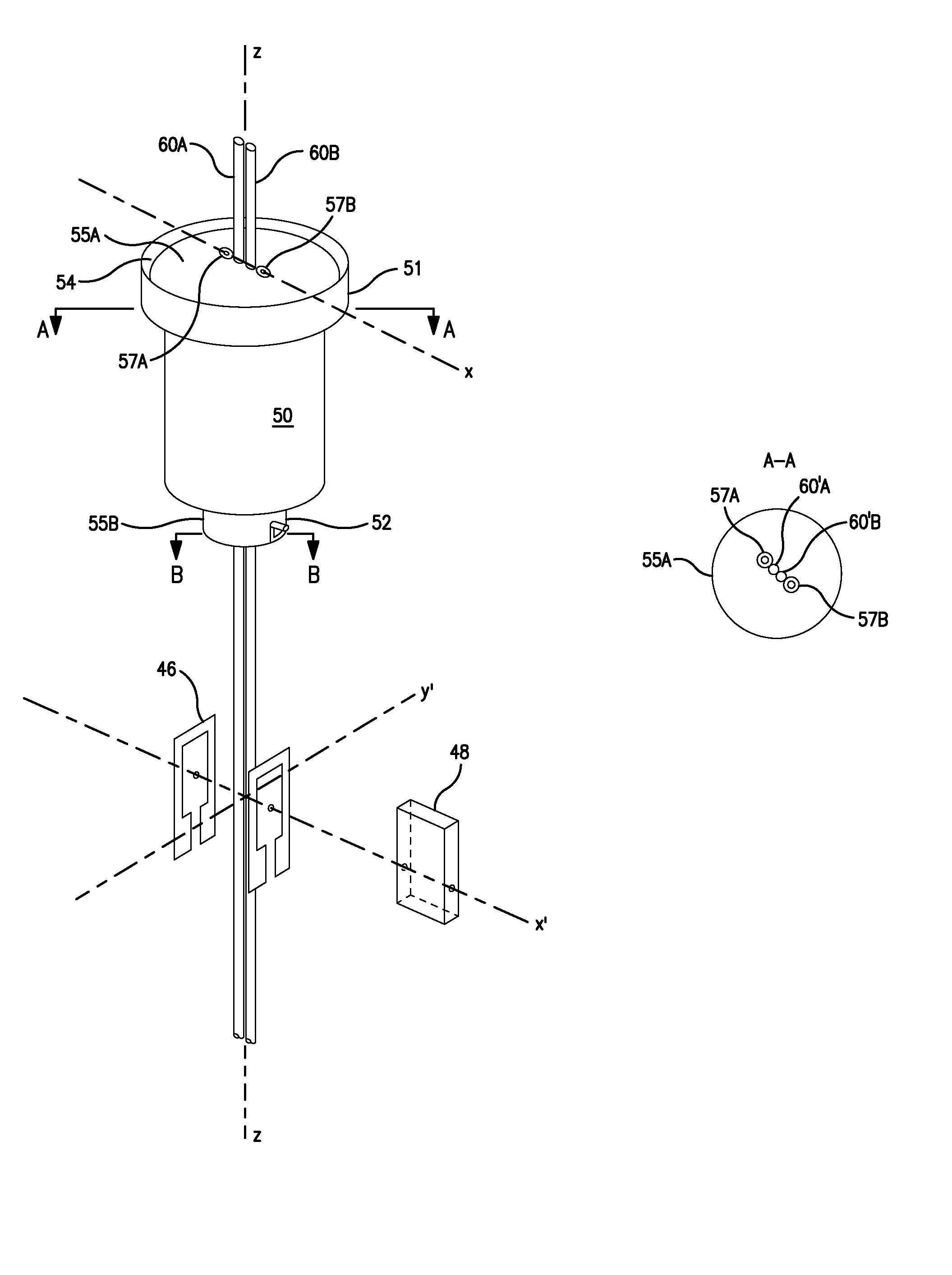
[0025]FIG. 3a shows a representative sample cell assembly for use with an NMR probe comprising a saddle coil 46 (here shown as one of the Alderman Grant variety) defining a sensitive volume 48 that is elongate in the plane transverse to the polarizing field. The sample cell assembly comprises a body 50 having an azimuthal reference 52 to obtain a selected azimuthal alignment of the body with respect to the saddle coil 46 of the NMR probe. Body 50 is characterized by axial geometry with body axis z coincident with the z axis of saddle coil 46. A cap portion 51 of the body 50 determines the axial relationship of body 50 with the sensitive volume 48 of the NMR probe, not otherwise illustrated. Each sample tube is maintained in the body 50 by frictional engagement with the outer surface of respective O-ring(s) 57A and 57B, which are in turn secured to the top alignment plate 55A through screws (not shown). The sample tubes are not otherwise constrained by passage through a bore through ...


PUM


Abstract

An elongate sample volume matching an elongate region of uniform RF magnetic field established by a saddle coil, is approximated by at least one pair of cylindrical sample tubes in parallel orientation with the geometric axis of the saddle coil. The displacement of the two cylindrical tubes defines a direction transverse to the tube axes and this transverse direction is aligned parallel with the RF magnetic field of the saddle coil.

Description

FIELD OF THE INVENTION[0001]This work is in the field of nuclear magnetic resonance analysis and particularly relates to sample cells for such analysis.BACKGROUND OF THE INVENTION[0002]Magnetic resonance phenomena occurs in a magnetic environment that is controllably homogeneous: uniform in magnitude, direction and stable in time. This environment is known as the polarizing field and imparts to the chaotically directed nuclear spins, a preferred direction in space around which the variously directed nuclear spins precess. Much effort has been directed to the production and control of the polarizing field.[0003]The resonant absorption of energy from an external source occurs through the agency of an RF magnetic field applied to the nuclei under study at an angle (preferably 90° to the polarizing field) through an RF resonator. Substantial effort has been expended to produce and control the homogeneity of this RF magnetic field associated with this resonator as experienced by and with...

Claims


Application Information

Patent Timeline
Patent Type & Authority Patents(United States)
IPC IPC(8): G01V3/00
CPCG01R33/34069G01R33/30
Inventor ZENS, ALBERT P.COSMAN, JASON WILLIAM
Owner AGILENT TECH INC
Why Eureka
Try Eureka