
Method for calibrating sensors

Inactive Publication Date: 2009-07-07
BSH BOSCH & SIEMENS HAUSGERAETE GMBH
View PDF4 Cites 1 Cited by
  • Summary
  • Abstract
  • Description
  • Claims
  • Application Information

AI Technical Summary

Benefits of technology

[0013]It is thus the object of the present invention to provide a method and a relevant domestic appliance for carrying out the method which allows sensors, e.g. turbidity sensors, to be calibrated reliably in a simple manner under all operating conditions of a domestic appliance, in particular, in the case of temporary contamination.
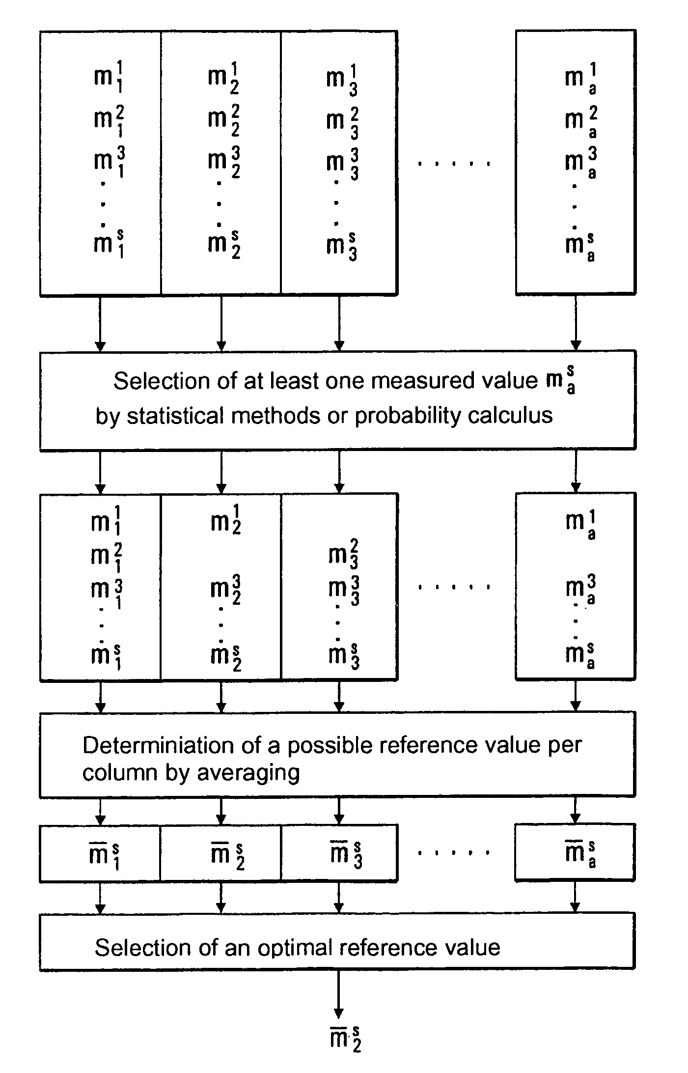
[0032]More appropriately, the at least one possible reference value for the calibration of the sensor is determined from the remaining non-selected measured values by selecting a measured value by means of statistical methods or probability calculus. This can eliminate errors resulting from individual incorrect measurements which may still be present because only one signal measured value is selected.
[0033]In a further variant, the measured value with the highest probability density within the non-selected measured values is selected. This can eliminate possible errors compared with averaging which is based on measured values which are possibly defective.

Problems solved by technology

However, the transmitting and receiving devices are subjected to changes from usage and ageing.
In addition, in some cases considerable deposits can occur on the optical devices.
Temporary impurities on the transmitting and receiving devices can lead to appreciable errors in the measurements.
In the course of time, this results in successively increasing errors in the measurements of the turbidity of the cleaning liquid.
This gives rise to errors in the control of the domestic appliance.
A disadvantage here is that if little intermediate rinsing is carried out or this is faded out, the rinsing solution can contain appreciable impurities during the clear rinsing so that the measurement results can be falsified.
Furthermore, only one adjusting measurement is made so that in the event of randomly occurring severe contamination, e.g. caused by localized deposits on the transmitting device, measured values for the adjustment of the measuring device with considerable errors are the consequence.
A disadvantage is that only a relatively small number of calibration measurements forms the basis for determining the reference value which is merely the average of a plurality of individual measurements within a wash program.
Consequently, sources of error which occur in several wash programs or only within an entire wash program, e.g. contamination on the optics of the transmitting device, cannot be identified.
As a result of determining the reference value by merely averaging from all the calibration measured values for each wash program, these calibration measured values frequently loaded with considerable errors are disadvantageously included in the averaging.

Method used


Image

  • Method for calibrating sensors
  • Method for calibrating sensors
  • Method for calibrating sensors

Examples


Embodiment Construction

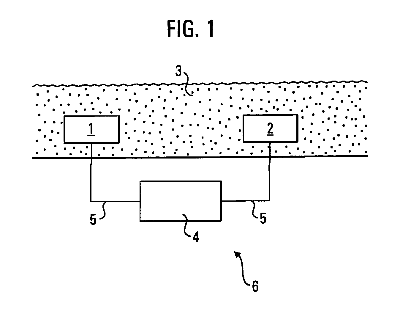
[0056]FIG. 1 is a schematic diagram showing a turbidity sensor 6. This has a transmitting device 1 in the form of a lamp which preferably emits visible light. The transmitting device 1 can also emit electromagnetic waves from other arbitrary frequency ranges, e.g. infrared light. In a receiving device 2 in the form of a photocell, the light incident thereon is converted into current. The washing solution 3 containing impurities is located between the transmitting device 1 and the receiving device 2. A control and evaluation unit 4 supplies the transmitted device 1 with current and evaluates the current delivered by the receiving device 2. The transmitting device 1 and the receiving device 2 are connected to the control and evaluation unit 4 via electrical leads 5. The control and evaluation unit 4 can also be part of the controller of a dishwasher according to the invention, i.e. a separate control and evaluation unit 4 is not required for the turbidity sensor 6. The degree of conta...


PUM


Abstract

A method for calibrating a sensor, particularly a turbidity sensor in a domestic appliance, such as a dishwasher or washing machine, with the aid of reference values, including the determination of measuring values, with at least one measured value selected using probability calculus that is no longer taken into account when determining the reference values.

Description

CROSS-REFERENCE TO RELATED APPLICATIONS[0001]Not ApplicableSTATEMENT REGARDING FEDERALLY SPONSORED RESEARCH OR DEVELOPMENT[0002]Not ApplicableTHE NAMES OF THE PARTIES TO A JOINT RESEARCH AGREEMENT[0003]Not ApplicableINCORPORATION-BY-REFERENCE OF MATERIAL SUBMITTED ON A COMPACT DISC[0004]Not ApplicableBACKGROUND OF THE INVENTION[0005]1. Field of the Invention[0006]The invention relates to a method for calibrating sensors, in particular turbidity sensors in domestic appliances, and a relevant domestic appliance for carrying out the method.[0007]2. Description of Related Art[0008]In domestic appliances, e.g. dishwashers or machine machines, turbidity sensors are used to determine the degree of contamination of the cleaning fluid, e.g. washing solution or washing liquid. Values of the degree of contamination determined by the turbidity sensor are used for further control of the cleaning program of the domestic appliance. In a dishwasher the cleaning program consists, for example, of the...

Claims


Application Information

Patent Timeline
IPC IPC(8): G06F19/00
CPCD06F39/004A47L15/4297D06F34/22D06F2103/20D06F2105/52
Inventor CURTIUS, GEORGFAUTH, MICHAELHERING, REINHARD
Owner BSH BOSCH & SIEMENS HAUSGERAETE GMBH
Learn More