Actuation system and method for an implantable infusion pump

a technology of infusion pump and actuation system, which is applied in the direction of infusion device, intravenous device, medical preparation, etc., can solve the problems of catheter incision point infection, risk of damage to the external pump, cumbersome and inconvenient,

Inactive Publication Date: 2009-07-14
ADVANCED NEUROMODULATION SYST INC
View PDF14 Cites 55 Cited by
  • Summary
  • Abstract
  • Description
  • Claims
  • Application Information

AI Technical Summary

Problems solved by technology

While external infusion pumps overcome some of the limitations of pills, injections, and suppositories, they are often cumbersome and inconvenient.
These devices must typically be worn or strapped to the patient, encumbering clothing selection, participation in activities such as bathing or swimming, and there is often a risk of damage to the external pump.
In addition, catheter incision points are subject to infection.
However, current versions of implantable infusion pump systems also have disadvantages.
Typically, implantable infusion pump systems provide limited patient control and safety features.
Many systems are limited to a single flow rate pre-programmed by a doctor.
In these systems, patients lack control of the system for responding to events.
However, with the present systems that have minimal or no control, the patient has no means of adjusting dosage rates to compensate for these or other events of pain increase.
In certain devices which provide patients with limited control, the systems often lack sufficient features to prevent overdose.
As a result, a patient may attempt to implement a second, third or fourth bolus dose, leading to an overdose situation.

Method used


Image

  • Actuation system and method for an implantable infusion pump
  • Actuation system and method for an implantable infusion pump
  • Actuation system and method for an implantable infusion pump

Examples


Embodiment Construction

[0028]Patient control of dosing permits adaptation of treatment to events and progressing conditions. In various cases, the safe addition of bolus or supplemental dosing features aids in management of treatment and reduces the consequences of inappropriate dosing. Safe administration of a bolus within prescribed limits permits patients to compensate for unusual events or conditions while preventing overdose. Similarly, safe administration of supplemental doses permits the patient to adapt treatment to routines or to heterogeneous or circadian conditions.

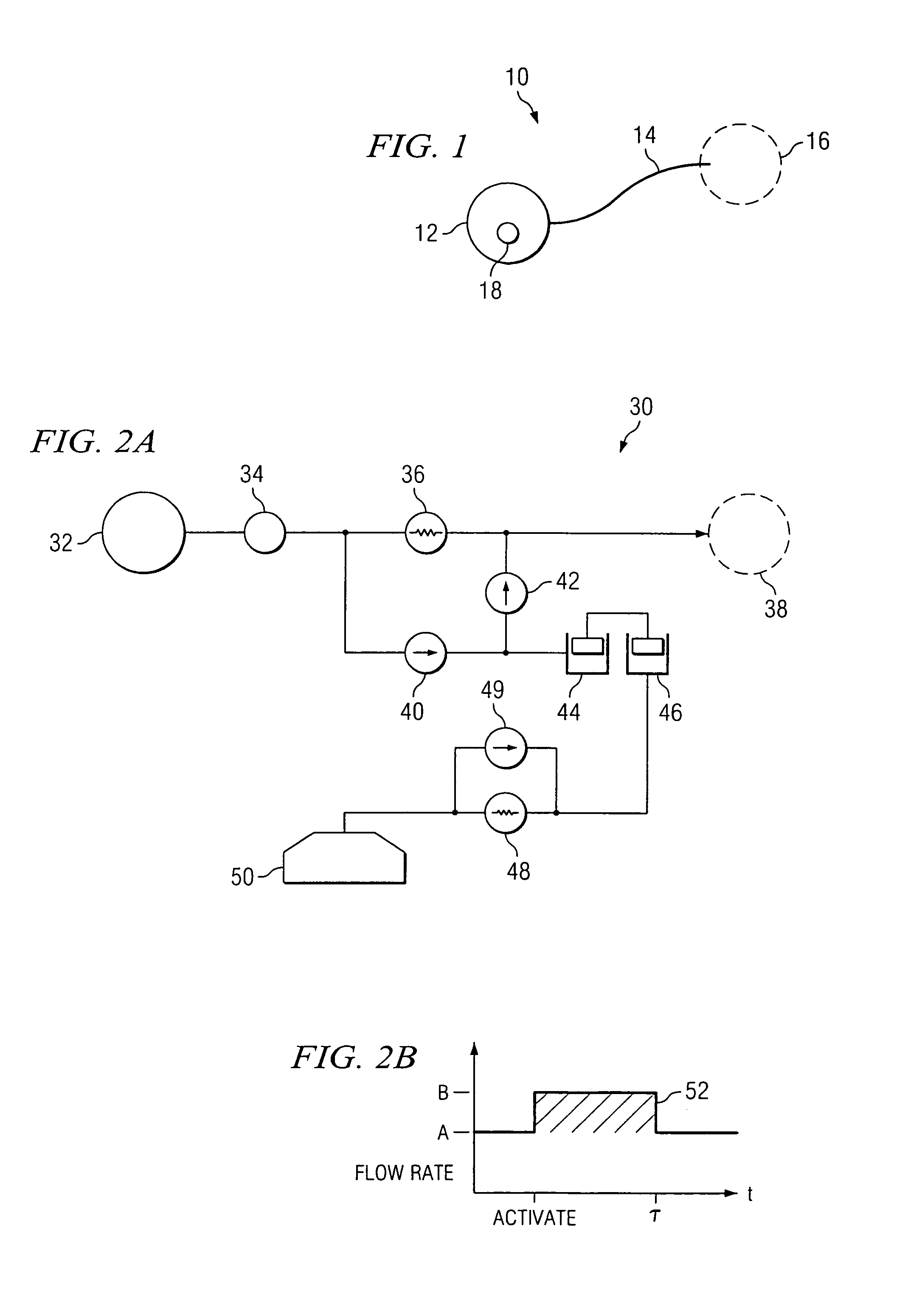
[0029]FIG. 1 is a schematic diagram of an exemplary embodiment. The delivery system 10 includes an implantable infusion system 12 which delivers a pharmaceutical solution through a catheter 14 to a treatment location 16. The implantable infusion system 12 includes an actuation system 18, which functions to augment flow through catheter 14 upon activation by a patient. Depending upon its purpose, actuator 18 may be located at various ...


PUM


Abstract

The invention relates to an actuation system and method for an implantable infusion pump. In an example, a working fluid is placed in an actuator. Upon actuation, the working fluid is driven into a piston cylinder. Upon deactuation, the actuator draws the fluid from the cylinder through a restrictor at a rate dictated by the motivating force, fluid viscosity, and restriction. Driving of the piston may produce a bolus dosage or fill a supplemental flow chamber for subsequent delivery. The exemplary system may be configured by selecting a fluid volume and a viscosity. These, in combination, produce a prescribed fluid delivery rate (or recharge rate) and cumulative flow volume provided to a patient over a time period or in a bolus dose. The system may also be configured to limit the total dosage of a bolus injection, or the rate of a supplemental dosage. In this manner, the system is safe, preventing overdose.

Description

CROSS-REFERENCE TO RELATED APPLICATIONS[0001]Priority is hereby claimed to U.S. Provisional Application No. 60 / 439,780, filed Jan. 13, 2003 and U.S. Provisional Application No. 60 / 439,909, filed Jan. 14, 2003, the disclosures of which are hereby incorporated herein by reference. The present application is related to the co-pending and commonly assigned U.S. patent application Ser. No. 10 / 756,673, titled “Multi-Stable Valves for Medical Applications and Methods for Use Thereof,” filed concurrently herewith, the disclosure of which is hereby incorporated herein by reference.TECHNICAL FIELD[0002]The invention in general relates to implantable infusion pumps. More specifically, the invention relates to actuation systems and methods for delivering supplemental drug dosages in continuous or bolus patterns from an implantable infusion system.BACKGROUND OF THE INVENTION[0003]Implantable drug infusion therapy has been used to treat various ailments including pain, spasticity, and cancer. The...

Claims


Application Information

Patent Timeline
Patent Type & Authority Patents(United States)
IPC IPC(8): A61K9/22
CPCA61M5/14276A61M5/14526A61M5/1428A61M2005/1405
Inventor BLISCHAK, BRIAN
Owner ADVANCED NEUROMODULATION SYST INC
Why Eureka
Try Eureka