Scanning laser microscope

a laser microscope and scanning laser technology, applied in the field of scanning laser microscopes, can solve the problems of inability to acquire a clear multi-photon fluorescence image, and inability to accurately detect the intensity of the laser beam

Active Publication Date: 2009-07-14
EVIDENT CORP
View PDF15 Cites 23 Cited by
  • Summary
  • Abstract
  • Description
  • Claims
  • Application Information

AI Technical Summary

Benefits of technology

[0008]The present invention provides a scanning laser microscope which can acquire a bright, clear multiphoton-fluorescence image containing no autofluorescence, while applying a stimulus with continuous laser light.

Problems solved by technology

However, ultrashort pulsed laser light sources are extremely expensive compared to continuous laser light sources.
Therefore, there is a drawback in that the autofluorescence intrudes into the multiphoton-fluorescence image acquired for observation.
As a result, there is a problem in that it is not possible to acquire a clear multiphoton-fluorescence image.

Method used


Image

  • Scanning laser microscope
  • Scanning laser microscope
  • Scanning laser microscope

Examples


Embodiment Construction

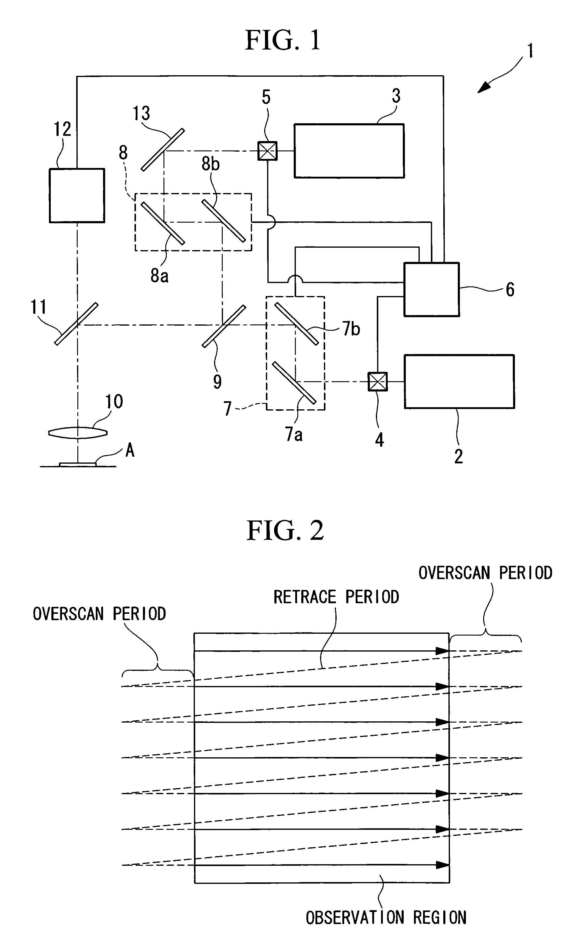
[0040]A scanning laser microscope 1 according to an embodiment of the present invention is described below with reference to FIGS. 1 to 10.

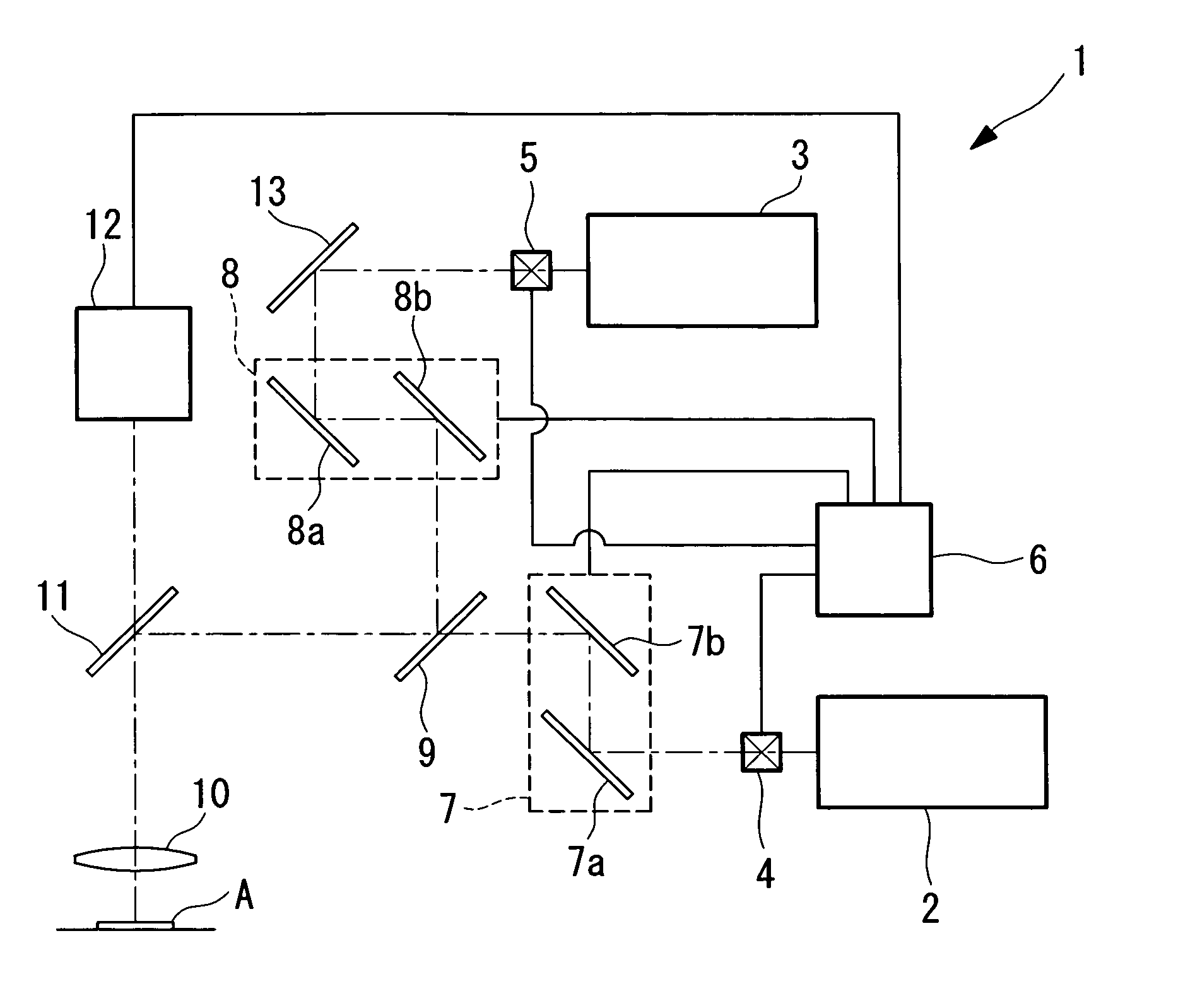
[0041]As shown in FIG. 1, the scanning laser microscope 1 according to this embodiment includes a first laser light source 2 for emitting ultrashort-pulsed laser light and a second laser light source 3 for emitting continuous laser light. A shutter 4 (pulsed-laser-light switching unit) and a shutter 5 (continuous-laser-light switching unit) are provided after the laser light sources 2 and 3, respectively.

[0042]The first laser light source 2 can selectively emit infrared pulsed laser light in a wavelength range of 820 to 1000 nm, for example.

[0043]The second laser light source 3 emits continuous laser light having wavelength of 405 nm, for example.

[0044]The shutters 4 and 5 are formed of acousto-optic devices such as AOMs or AOTFs, or electro-optic devices.

[0045]The shutters 4 and 5 are connected to a control unit 6. The control unit 6 controls th...


PUM

PropertyMeasurementUnit
wavelength rangeaaaaaaaaaa
wavelengthaaaaaaaaaa

Abstract

Provided is a scanning laser microscope including a first laser light source for emitting ultrashort pulsed laser light; a scanning unit for two-dimensionally scanning the ultrashort pulsed laser light on a specimen; a second laser light source for emitting continuous laser light; an irradiation-position adjusting unit for performing two-dimensional adjustment of an irradiation position of the continuous laser light on the specimen; an objective lens for focusing the ultrashort pulsed laser light and the continuous laser light onto the specimen and for collecting fluorescence generated in the specimen; a light-detecting unit for detecting the fluorescence, which is split off from a light path between the objective lens and the scanning unit; and a continuous-laser-light switching unit for permitting radiation of the continuous laser light when the light-detecting unit is not detecting required fluorescence from the specimen on the basis of the ultrashort pulsed laser light.

Description

BACKGROUND OF THE INVENTION[0001]1. Field of the Invention[0002]The present invention relates to scanning laser microscopes.[0003]This application is based on Japanese Patent Application No. 2007-025782, the content of which is incorporated herein by reference.[0004]2. Description of Related Art[0005]A known scanning laser microscope in the related art is provided with two scanners. One scanner is used to scan ultrashort pulsed laser light onto a specimen, and multiphoton fluorescence generated by a multiphoton-excitation effect in the specimen is observed. The other scanner is used to radiate the ultrashort pulsed laser light at a specific position on the specimen for applying a light stimulus. (For example, see Japanese Unexamined Patent Application, Publication No. 2006-3521.)[0006]The scanning laser microscope disclosed in Japanese Unexamined Patent Application, Publication No. 2006-3521, uses the multiphoton excitation effect due to the ultrashort pulsed laser light for both ob...

Claims


Application Information

Patent Timeline
Patent Type & Authority Patents(United States)
IPC IPC(8): G01N21/64
CPCG02B21/002G02B21/16G02B2207/113
Inventor KIMURA, HIROYUKIKUSAKA, KENICHIISHIHARA, KATASHI
Owner EVIDENT CORP
Why Eureka
Try Eureka