Power amplifier with controlled output power

a power amplifier and output power technology, applied in the direction of amplifiers, gain control, amplifiers with diodes, etc., can solve the problems of temperature, manufacturing process tolerance, power supply voltage variation, etc., and achieve the effect of reducing manufacturing process tolerance, improving power supply voltage, and improving power supply voltag

Active Publication Date: 2009-07-14
EM MICROELECTRONIC-MARIN
View PDF2 Cites 5 Cited by
  • Summary
  • Abstract
  • Description
  • Claims
  • Application Information

AI Technical Summary

Problems solved by technology

Nevertheless existing power amplifier control techniques are sensitive to temperature, manufacturing process tolerances and power supply voltage variations.

Method used


Image

  • Power amplifier with controlled output power
  • Power amplifier with controlled output power
  • Power amplifier with controlled output power

Examples


Embodiment Construction

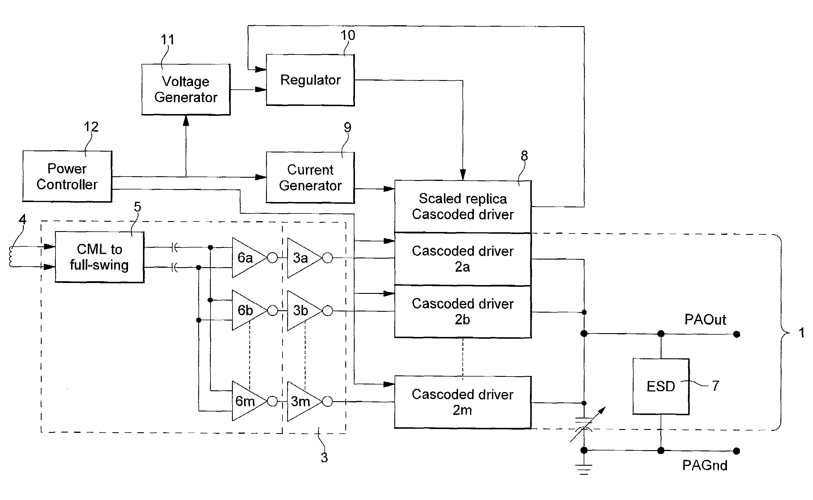
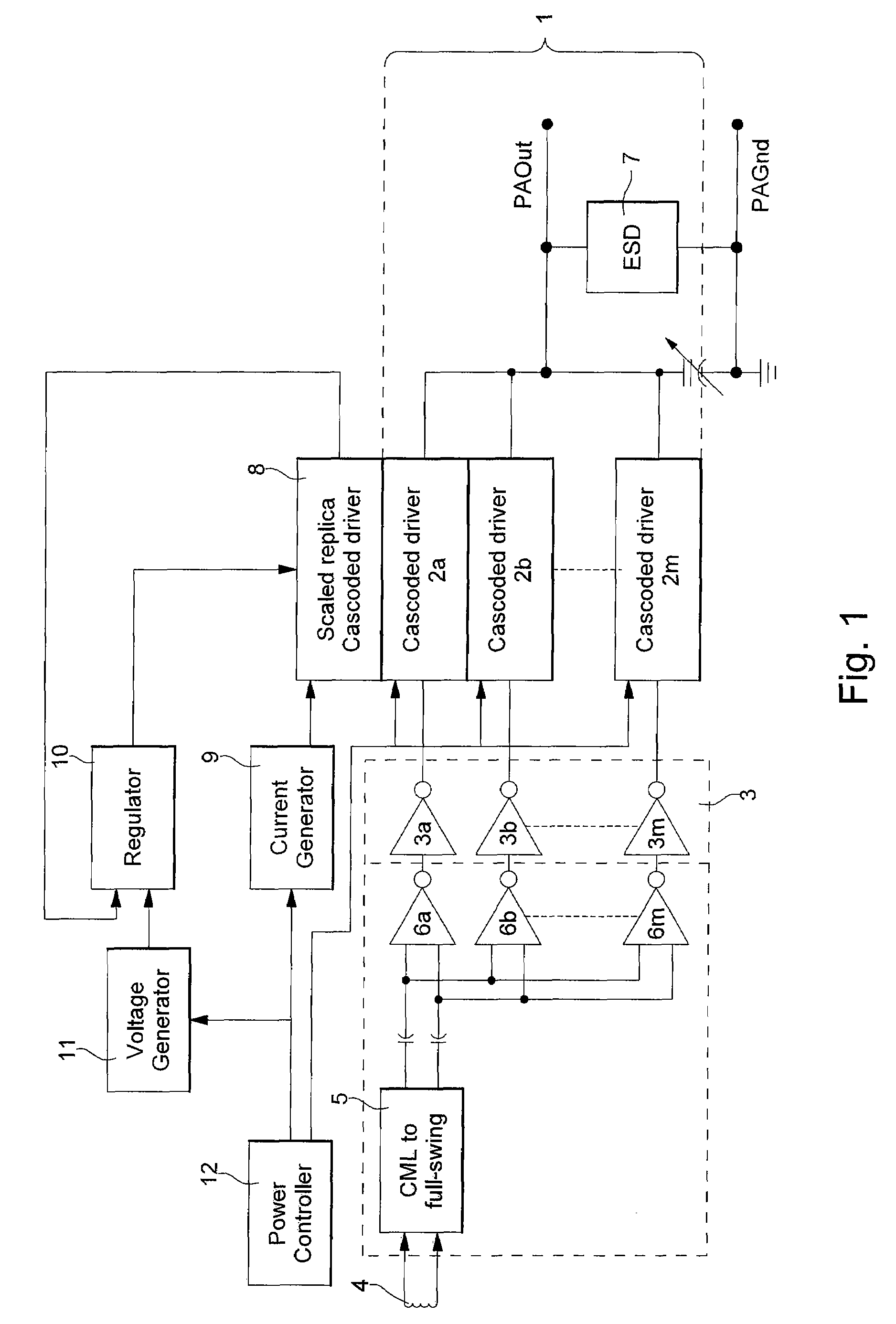
[0013]The following description of a power amplifier with control output power is given by way of a non limiting example in relation with FIGS. 1 to 3.

[0014]FIG. 1 shows the overall block diagram of the power amplifier according to a preferred embodiment of the invention. The power amplifier core 1 consists in parallel amplifier cells 2a-2m, preferably cascoded amplifiers or as labelled “cascoded drivers” each being controlled by the means of a corresponding drive gate 3a-3m. When operating the amplifier core 1 functions as a class C type amplifier by pulling current from a load during a portion of one period of the output frequency, e.g. an antenna 4 connected at the terminals of a Current-Mode Logic to full swing unit 5 connected in turn to inverters 6a-6m to distribute the pulled load to amplifier core 1 via drive gates 3a-3m. The current pulled from load 4 may be controlled by the amplitude and / or width of the pulse on the drive gate 3a-3m of cascoded drivers 2a-2m. In fact, in ...


PUM


Abstract

The invention includes a power amplifier with an amplifier core including parallel amplifier cells, a replica cell made of one amplifier cell similar to those of the amplifier core, a power controller to select a combination of amplifier cells to activate, a regulator to fix the top voltage of the replica cell to a reference voltage, a voltage generator to provide the voltage reference to the regulator, a current generator to provide a reference current through the replica cell, and a drive unit controlled by the regulator output to drive the combination of amplifier cells, so that each selected combination of activated cells defines a predetermined attenuation level of power amplifier output signal so that it is attenuated in a stepwise manner.

Description

FIELD OF THE INVENTION[0001]The present invention generally relates to RF power devices, in particular to power amplifiers with a controlled output power.BACKGROUND OF THE INVENTION[0002]Product manufacturers have a need to control output power from RF power devices. This allows them to optimize performances such as transmission range and battery life and at the same time not to violate government regulations dealing with power emissions. For that purpose, power amplifiers known in the art are usually based on methods that control gate or base drive, adjust bias current or parallel devices together to perform power control.[0003]Nevertheless existing power amplifier control techniques are sensitive to temperature, manufacturing process tolerances and power supply voltage variations.SUMMARY OF THE INVENTION[0004]One goal of the present invention is thus to carry out a reliable and simple controlled power amplifier which overcomes the drawbacks of the prior art. For that purpose, it i...

Claims


Application Information

Patent Timeline
Patent Type & Authority Patents(United States)
IPC IPC(8): H03F3/10
CPCH03F1/0277H03F1/223H03F3/72H03F3/211H03F2203/7236H03F2200/453
Inventor BUESCHER, KEVIN SCOTTPARDOEN, MATTHIJS
Owner EM MICROELECTRONIC-MARIN
Why Eureka
Try Eureka