Printed antenna and a wireless network device having the antenna

a wireless network device and printed antenna technology, applied in the field of printed antennas, can solve the problems of inadequate isolation between adjacent antennas, and achieve the effects of improving radiation pattern, improving isolation, and increasing gain

Inactive Publication Date: 2009-07-14
CAMEO COMM
View PDF7 Cites 11 Cited by
  • Summary
  • Abstract
  • Description
  • Claims
  • Application Information

AI Technical Summary

Benefits of technology

[0007]The first object of the present invention is to provide a printed antenna with better radiation pattern to improve gain and reduce dead space and having better antenna-to-antenna isolation to avoid interference and enhance antenna performance.
[0009]The third object of the present invention is to provide a printed antenna for MIMO wireless networking device which includes three antennas with two adjacent antennas extending in approximately vertical arrangement to improve the antenna-to-antenna isolation.
[0011]To achieve the aforesaid objects, the printed antenna of the present invention changes its middle antenna in the three-antenna configuration of the MIMO antenna unit to a T-dipole antenna and arranges the two monopole antennas on each side of the T-dipole in a direction generally vertical to the T-dipole. Such arrangement is different from the conventional three-antenna system where all three antennas are adjacent to each other and face the same direction. As such, in the printed antenna of the invention, the T-dipole antenna which itself is a radiator and the grounding member configured between the T-dipole and the monopole antenna helps enhance the isolation between two adjacent antennas. In addition, the design of a T-dipole antenna coupled with a monopole antenna on each side extending in different direction can produce better radiation pattern on X-Y plane and higher gain, hence greatly improving the antenna performance.

Problems solved by technology

A major drawback in this kind of conventional MIMO antenna unit 24 is that its three monopole antennas 241, 242, 243 are arranged next to each other and extend in the same direction, resulting in inadequate isolation between adjacent antennas (e.g. between first antenna 241 and second antenna 242).

Method used


Image

  • Printed antenna and a wireless network device having the antenna
  • Printed antenna and a wireless network device having the antenna
  • Printed antenna and a wireless network device having the antenna

Examples


Embodiment Construction

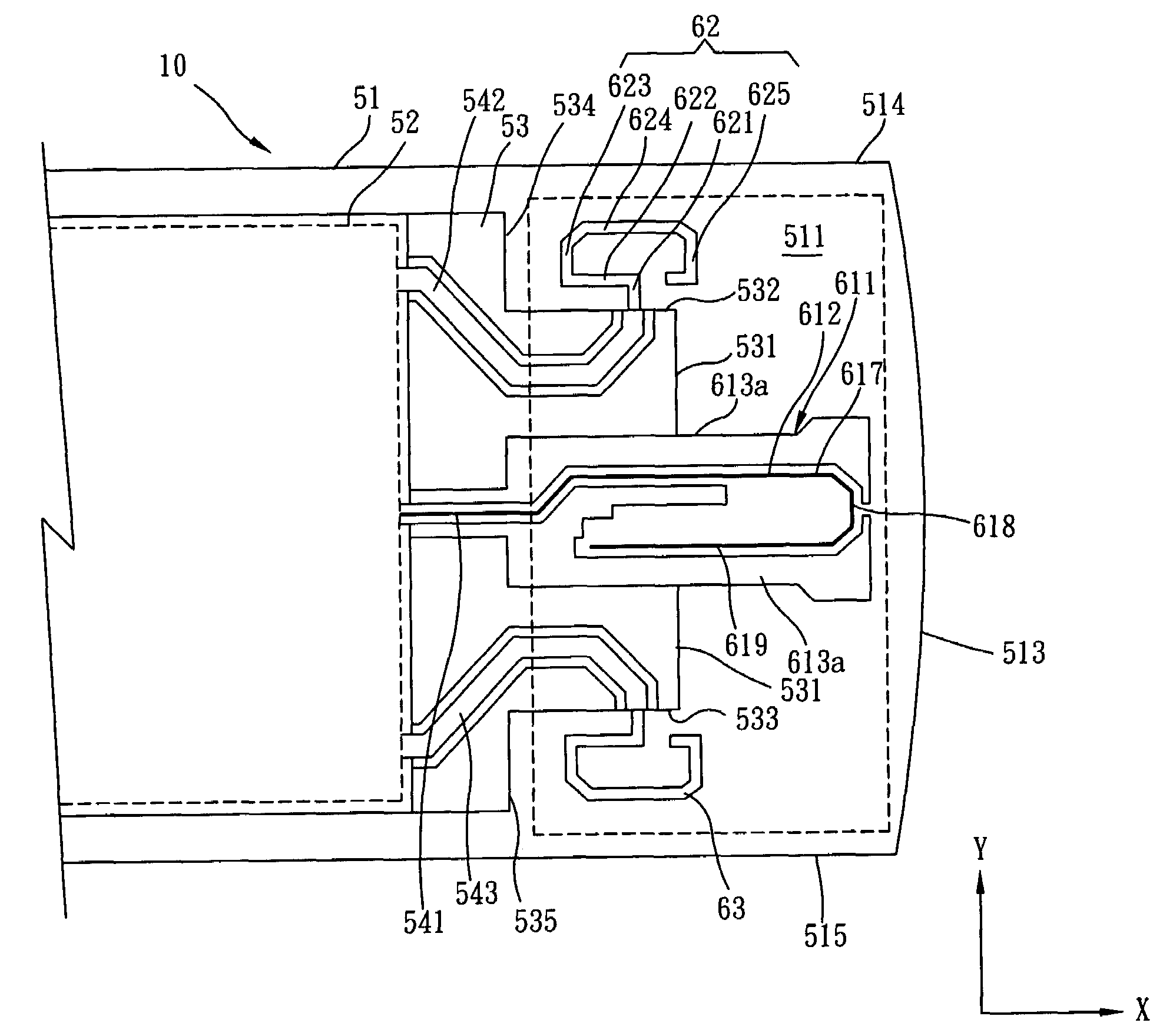
[0022]FIGS. 5˜7 disclose a preferred embodiment of the printed antenna 60 and a wireless networking device 50 having printed antenna 60 according to the invention. FIG. 5 and FIG. 6 show respectively the component side and the solder side of the internal circuitry of the wireless networking device 50 having a printed antenna 60 according to the invention. FIG. 7 is a magnified view of the printed antenna 60 in the wireless networking device shown in FIG. 5 and FIG. 6.

[0023]As shown in FIG. 5, the wireless networking device 50 having a printed antenna 60 according to a preferred embodiment of the invention comprises: a base plate 51, a control circuit 52, a grounding member 53 and a printed antenna 60.

[0024]The base plate 51 is made of dielectric material in the shape of a generally flat rectangle. In a preferred embodiment, the base plate 51 is a FR4 circuit board. The base plate 51 has a component side surface disposed with a plurality of electronic circuits (called first surface 5...


PUM


Abstract

A printed antenna suitable for wireless networking device comprising a base plate, a grounding member, a first antenna, a second antenna and a third antenna is disclosed. The base plate is made of dielectric material where on a surface of which a first direction and a second direction perpendicular to each other are defined. The grounding member is electrically grounded and covers at least a partial area of the base plate surface. The first antenna is a dipole antenna extending from the grounding member generally towards the first direction. The second antenna is a monopole antenna extending from the grounding member generally towards the second direction. The third antenna is a monopole antenna extending from the grounding member generally towards the second direction. The second antenna and the third antenna are substantially disposed on the two opposing sides of first antenna.

Description

BACKGROUND OF INVENTION[0001]1. Field of the Invention[0002]The present invention relates to a kind of printed antenna, more particularly a printed antenna suitable for MIMO wireless networking device and a wireless networking device having the same.[0003]2. Description of the Prior Art[0004]FIG. 1 depicts the perspective view of a typical wireless networking device 10, comprising a body 11, internal circuitry 12 disposed inside the body, a connecting member 13 disposed at one end of body 11 to connect an external host (not shown in the figure), and an antenna signal transceiver 14 arranged on the other end of body 11 and corresponding to the connecting member 13. Generally, the shell of antenna signal transceiver 14 is made of non-metallic material. When the wireless networking device 10 is connected to an external host, the antenna signal transceiver 14 must be exposed outside the external host for effective receiving and transmission of wireless signals. Based on the practice of ...

Claims


Application Information

Patent Timeline
Patent Type & Authority Patents(United States)
IPC IPC(8): H01Q1/24
CPCH01Q1/2275H01Q1/38H01Q21/29H01Q9/42H01Q9/285
Inventor CHEN, YU REN
Owner CAMEO COMM
Why Eureka
Try Eureka