Liquid crystal display device

a liquid crystal display and display device technology, applied in non-linear optics, instruments, optics, etc., can solve the problems of poor heat dissipation and damage to the light source, and achieve the effect of improving heat dissipation and less likely to be damaged

Active Publication Date: 2009-07-14
JAPAN DISPLAY WEST
View PDF3 Cites 8 Cited by
  • Summary
  • Abstract
  • Description
  • Claims
  • Application Information

AI Technical Summary

Benefits of technology

[0007]In view of the conventionally experienced disadvantages described above, it is an object of the present invention to provide a liquid crystal display device that offers improved heat dissipation and that can prevent a light source from being damaged when such a liquid crystal display device is vibrated or dropped.
[0009]As described above, the reinforcing member is provided between the one side face of the light guide plate and the holder, and the shock-absorbing member that makes contact with or lies adjacent to the side face of the reinforcing member is provided. As a result, even when the light guide plate is moving toward the holder when the liquid crystal display device is vibrated or dropped, the reinforcing member having the shock-absorbing member prevents such movement. This prevents the light source housed in the holder from being exposed to external pressure, making the light source less likely to be damaged.
[0010]According to the present invention, since a radiator plate on which the light guide plate and the reflecting plate are laid is exposed through an opening of the frame body, heat given off by the light source is released into the outside air through a three-layer structure composed of the light guide plate, the reflecting plate, and the radiator plate. This improves heat dissipation.

Problems solved by technology

A first disadvantage of the liquid crystal display device described above is poor heat dissipation.
Furthermore, a second disadvantage of the liquid crystal display device described above is that, in a case where a plurality of such liquid crystal display devices are transported by truck or the like, the light guide plate moves from side to side and often causes damage to the light source.

Method used


Image

  • Liquid crystal display device
  • Liquid crystal display device
  • Liquid crystal display device

Examples


embodiment 1

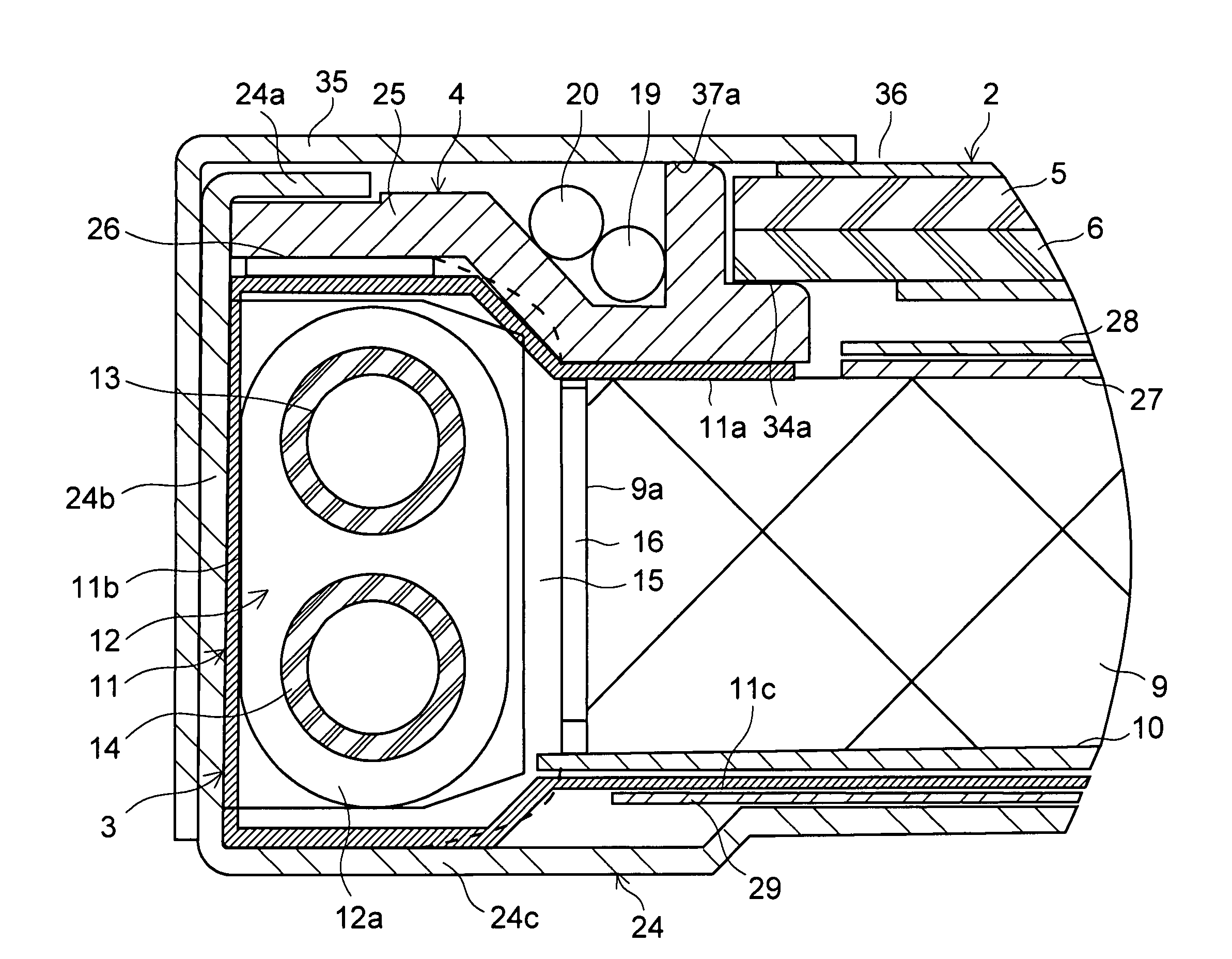
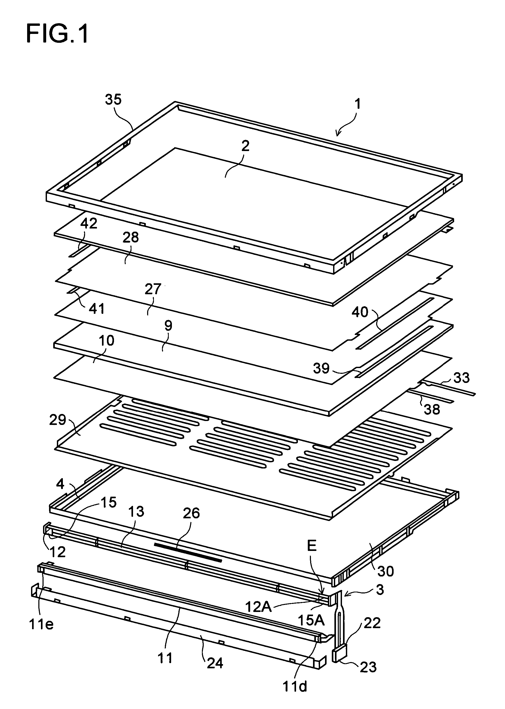
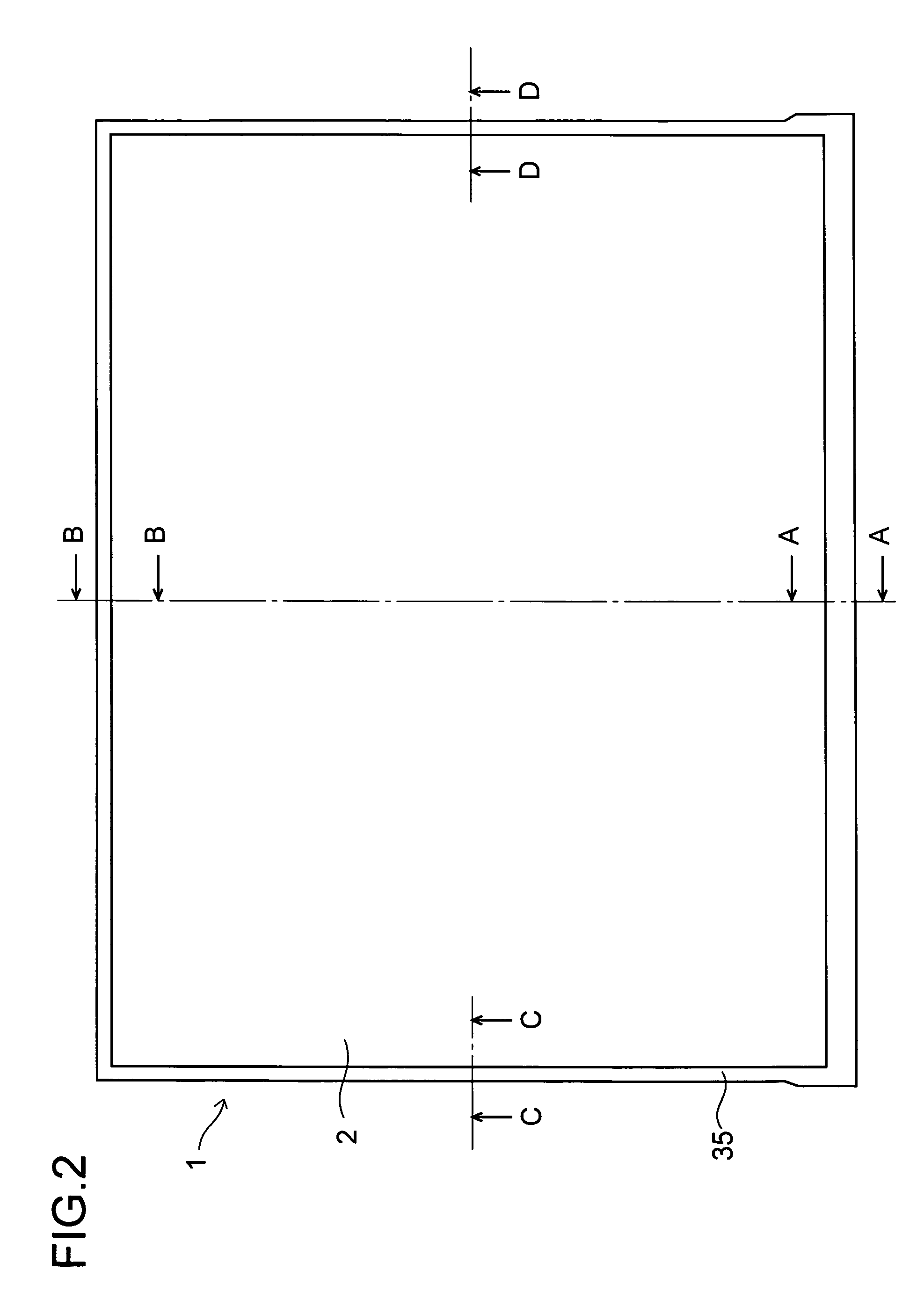
[0025]FIG. 1 is an exploded perspective view of a liquid crystal display device 1 embodying the present invention. FIG. 2 is a front view of the liquid crystal display device 1 (in a completely assembled state). FIGS. 3, 4, 5, and 6 are sectional views taken on the lines A-A, B-B, C-C, and D-D, respectively, of FIG. 2. FIG. 7 is a perspective view from the direction indicated by arrow E shown in FIG. 1.

[0026]As shown in these figures, the liquid crystal display device 1 is composed of, for example, a liquid crystal cell 2, illuminating means 3, and a frame body that supports the liquid crystal cell 2 and the illuminating means 3.

[0027]The liquid crystal cell 2 is built with a pair of glass substrates 5 and 6 bonded together with a sealing material (not shown) applied near the peripheries thereof, and liquid crystal sealed between them.

[0028]Furthermore, one glass substrate 6 has a plurality of unillustrated terminals to which a plurality of TCPs (tape carrier packages) 7 having moun...

embodiment 2

[0079]Next, a second embodiment that differs from the first embodiment in a shock-absorbing member will be described. FIG. 11 is a sectional view of one holder portion 12, FIG. 12 is a perspective view of the first supporting member 4′ showing the shock-absorbing member 16′, and FIG. 13 is a perspective view of the shock-absorbing member 4′ of FIG. 12 but viewed in different direction. The first embodiment described above deals with a case where the left and right shock-absorbing members 16 and 16A are fixed to the left and right reinforcing members 15 and 15A, respectively, with an adhesive. In the second embodiment, the shock-absorbing members 16′ and 16′A extend from the first supporting member 4′ and are not bonded to the reinforcing members 15 and 15A. As a result of the shock-absorbing members 16′ and 16′A being formed integrally with the supporting member 4′, they are made of plastic.

[0080]Here, the benefits offered by the second embodiment will be described. As is the case o...


PUM

PropertyMeasurementUnit
widthaaaaaaaaaa
lengthaaaaaaaaaa
heat dissipationaaaaaaaaaa

Abstract

Provided is a liquid crystal display device that offers improved heat dissipation and that can prevent a light source from being damaged when such liquid crystal display device is vibrated or dropped. The liquid crystal display device is provided with a liquid crystal cell 2, illuminating means 3 that is located behind the liquid crystal cell 2, and a frame body 4 that supports the liquid crystal cell 2 and the illuminating means 3. The illuminating means 3 includes a light guide plate 9, light sources 13 and 14 that are located so as to face one side face of the light guide plate 9, and a holder 12 that supports the light sources 13 and 14. There is provided a reinforcing member 15 between the light guide plate 9 and the holder 12, and there is provided a shock-absorbing member 16 located on a side face of the reinforcing member 15 and that makes contact with or lies adjacent to the one side face of the light guide plate 9.

Description

[0001]This application is based on Japanese Patent Applications Nos. 2005-374332 and 2006-269554 filed on Dec. 27, 2005 and Sep. 29, 2006 respectively, the contents of which are hereby incorporated by reference.BACKGROUND OF THE INVENTION[0002]1. Field of the Invention[0003]The present invention relates to a liquid crystal display device.[0004]2. Description of Related Art[0005]A conventionally known example of such a liquid crystal display device is disclosed, for example, in JP-A-2005-037814. The liquid crystal display device disclosed in this publication is provided with a box-shaped rear frame, a reflecting plate provided thereon, illuminating means, a liquid crystal cell, and a front-face frame. Outside the rear frame, a radiator plate is fixed in such a way as to cover the rear frame.[0006]A first disadvantage of the liquid crystal display device described above is poor heat dissipation. Through a study in search of the causes, the inventors of the present invention have found...

Claims


Application Information

Patent Timeline
Patent Type & Authority Patents(United States)
IPC IPC(8): G02F1/1333
CPCG02F1/133608G02F2001/133628G02F1/133628
Inventor NAKAGAWA, TAIJIMURAOKA, YUKINISHIMOTO, TAKUYANOBEOKA, KENSUKE
Owner JAPAN DISPLAY WEST
Why Eureka
Try Eureka