Methods of network routing having improved resistance to faults affecting groups of links subject to common risks

a network routing and fault technology, applied in the field of network routing, can solve the problems of increasing the size and complexity of the communication network, difficulty in routing paths between numerous source and destination nodes that meet various constraints, and insufficient use of suurballe-type techniques

Active Publication Date: 2009-07-14
WSOU INVESTMENTS LLC
View PDF5 Cites 13 Cited by
  • Summary
  • Abstract
  • Description
  • Claims
  • Application Information

AI Technical Summary

Problems solved by technology

With the advent of the Internet and its exponential growth, communication networks are increasing in size and complexity and moving toward using optical networks to provide very high speed interconnection bandwidth of the order of gigabits to terabits per second.
Due to the size and complexity of many communication networks, routing paths between numerous source and destination nodes that meet various constraints is a difficult problem.
Some of the constraints considered, for example, are performance, in terms of path distance and bandwidth, costs, such as fiber and equipment costs, and link and node failure probabilities.
The problem of finding routing paths in a physical network corresponds to finding paths in the directed or undirected graph.
Since many characteristics of physical networks are not easily abstracted to a graph, using techniques such as described by Suurballe are not adequate, especially when considering failure potentials in physical networks.

Method used


Image

  • Methods of network routing having improved resistance to faults affecting groups of links subject to common risks
  • Methods of network routing having improved resistance to faults affecting groups of links subject to common risks
  • Methods of network routing having improved resistance to faults affecting groups of links subject to common risks

Examples


Embodiment Construction

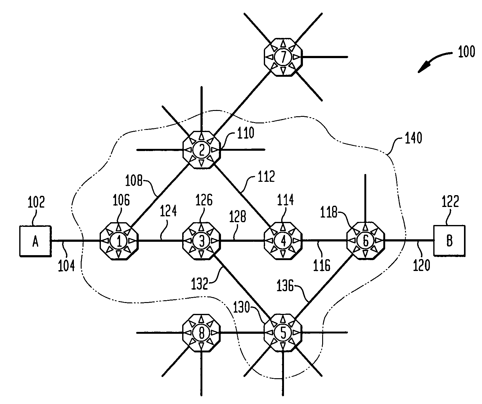
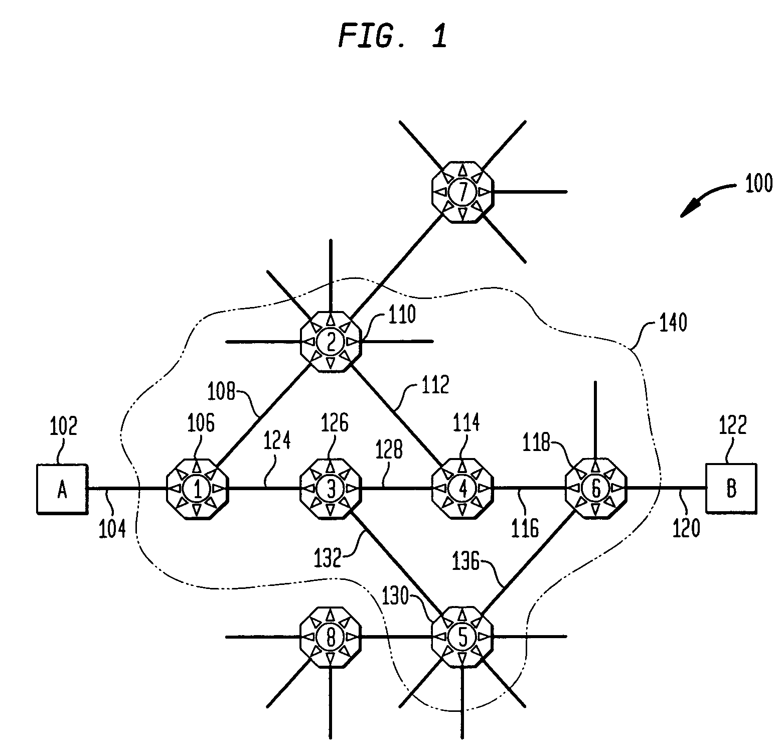
[0024]FIG. 1 shows a physical network of connection nodes connected by links. In FIG. 1, the physical network is embodied as an optical network made up of optical switch nodes connected by optic fiber links in a general mesh topology.

[0025]Links 104 and link 120 are considered to be standard interface connections, which may be optical connections, to access node devices A 102 and B 122, respectively. The links, such as 108, 112, 116, 124, 128, 132, and 136, are considered to use optical fibers that may carry multiple optical channels. The nodes 106, 110, 114, 118, 126, and 130 are optical switch nodes that can switch an incoming light path to an outgoing light path. Since optical switches are designed to be redundant, the typical type of failure that occurs in optical networks is damage to the fiber optic lines.

[0026]A particular example of a routing problem is the problem of finding a disjoint pair of paths in FIG. 1 between node 1106 and node 6118. The physical network, represente...


PUM


Abstract

A number of techniques are described for routing methods that improve resistance to faults affecting groups of links subject to common risks. One of these techniques accounts for failure potentials in physical networks by considering shared risk link groups separately from performance and costs metrics in determining a primary routing path and a backup path. A shared risk link group (SRLG) is an attribute attached to a link to identify edges that have physical links in common and can therefore be simultaneously disrupted due to a single fault. Another technique considers node disjointness and provides a solution of two paths that are as node disjoint as possible and minimizes administrative costs. The techniques may further be combined in a priority order thereby providing a solution of at least two paths that are strictly SRLG disjoint, as node-disjoint as possible, and have minimum administrative costs. Due to the priority order of evaluation and typical network physical configurations of links, with the links associated common fault SRLGs, the priority ordering technique is very efficient in determining at least two paths for routing between a source and destination node.

Description

FIELD OF INVENTION[0001]The present invention relates generally to routing methods for determining paths in interconnection networks for communication or computer use.BACKGROUND OF INVENTION[0002]Communication networks take many forms for interconnecting a source node to a destination node. With the advent of the Internet and its exponential growth, communication networks are increasing in size and complexity and moving toward using optical networks to provide very high speed interconnection bandwidth of the order of gigabits to terabits per second. An optical network generally consists of optical switch nodes and fiber optic interconnection links between nodes arranged in a general mesh topology. Due to the size and complexity of many communication networks, routing paths between numerous source and destination nodes that meet various constraints is a difficult problem. Some of the constraints considered, for example, are performance, in terms of path distance and bandwidth, costs,...

Claims


Application Information

Patent Timeline
Patent Type & Authority Patents(United States)
IPC IPC(8): H04L12/28
CPCH04L45/00H04L45/123H04L45/28H04L45/22H04L45/124H04L45/247
Inventor ALICHERRY, MANSOOR ALI KHANSANIEE, IRAJSENGUPTA, SUDIPTA
Owner WSOU INVESTMENTS LLC
Why Eureka
Try Eureka