
Dust proof sliding device

a technology of sliding device and dust proof, which is applied in the direction of mechanical equipment, transportation and packaging, etc., to achieve the effects of reducing the overall length, long-lasting durability, and high accuracy

Active Publication Date: 2009-07-21
NIPPON THOMPSON
View PDF10 Cites 16 Cited by
  • Summary
  • Abstract
  • Description
  • Claims
  • Application Information

AI Technical Summary

Benefits of technology

The solution achieves a compact, durable, and highly effective dust-proof sliding device that maintains high air cleanliness standards (class 2) and allows for easy installation in constrained spaces, ensuring minimal dust and dirt contamination.

Problems solved by technology

Making the sliding unit shorter in overall axial length while maintaining airtightness, thus, was a major challenge for this sort of sliding device.

Method used


Image

  • Dust proof sliding device
  • Dust proof sliding device
  • Dust proof sliding device

Examples


Embodiment Construction

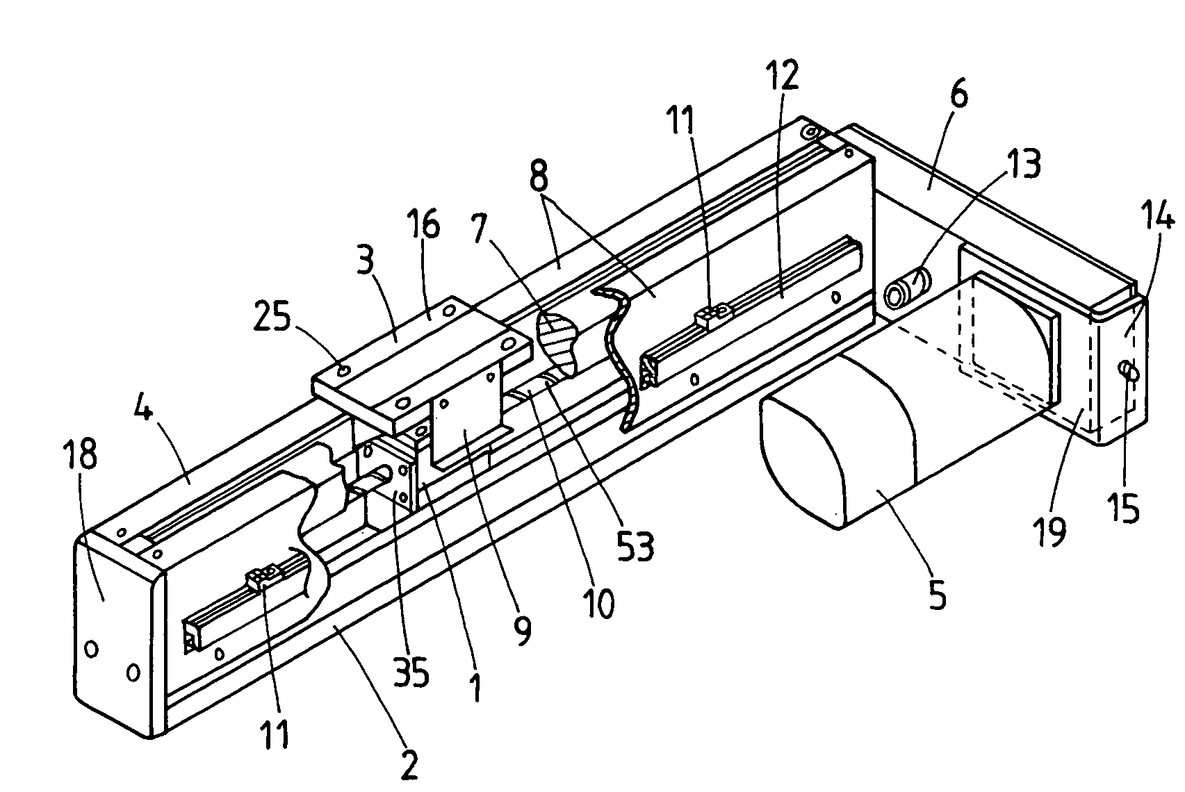
[0035]The sliding device of the present invention will be well used in not only a diversity of machinery including semiconductor manufacturing apparatus, machine tools, various assembling apparatus, precision testing / measuring instruments, position control tables, sliding tables and so on, which are needed to work in any controlled atmosphere including clean rooms, laboratories and the like, but also other types of machines that are expected to in reverse work in an environment contaminated with dust and dirt. The current sliding devices used in the advanced instruments installed in machinery operated in clean atmosphere are increasingly needed to match the working environment that detests causing any dust and dirt.

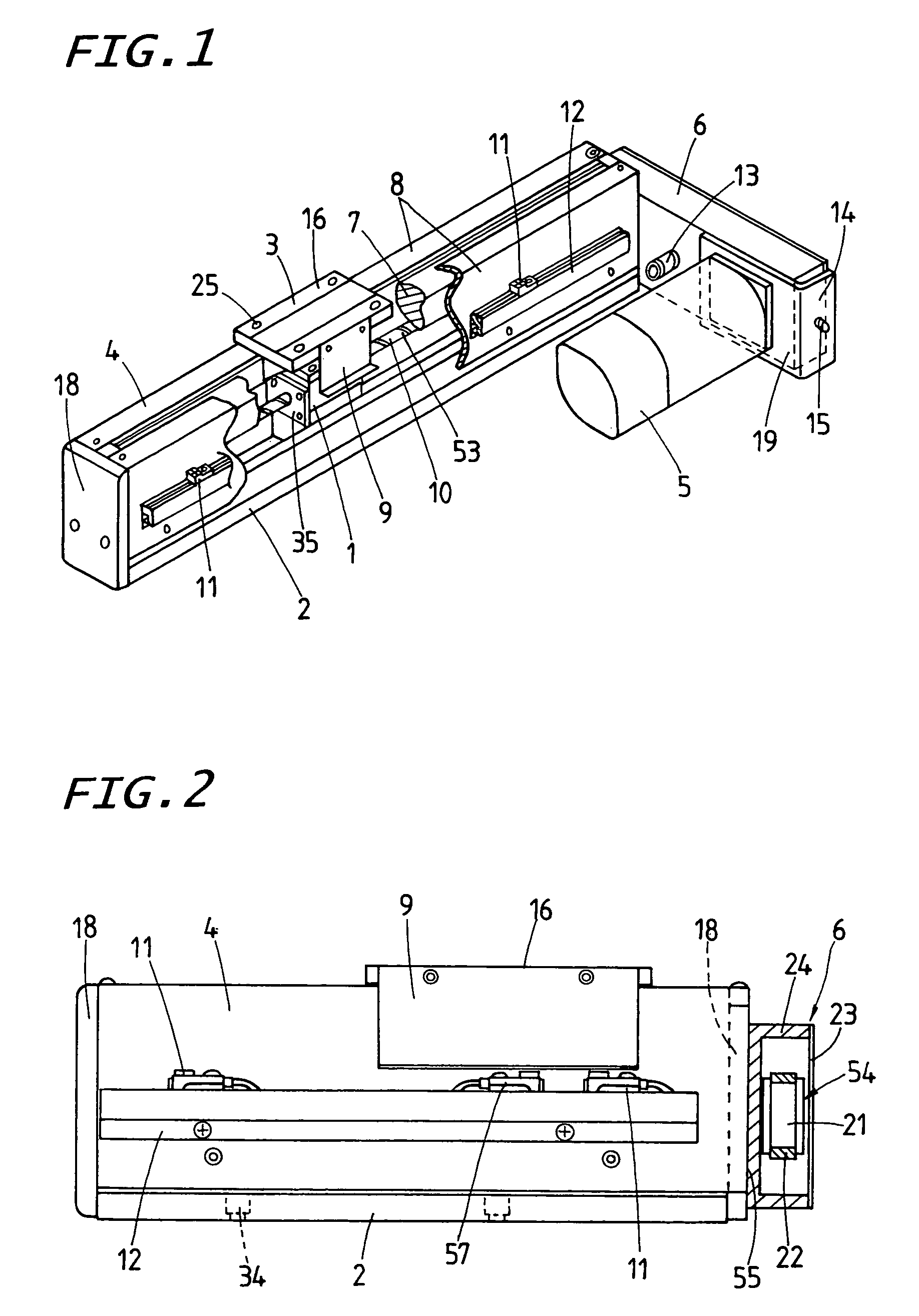
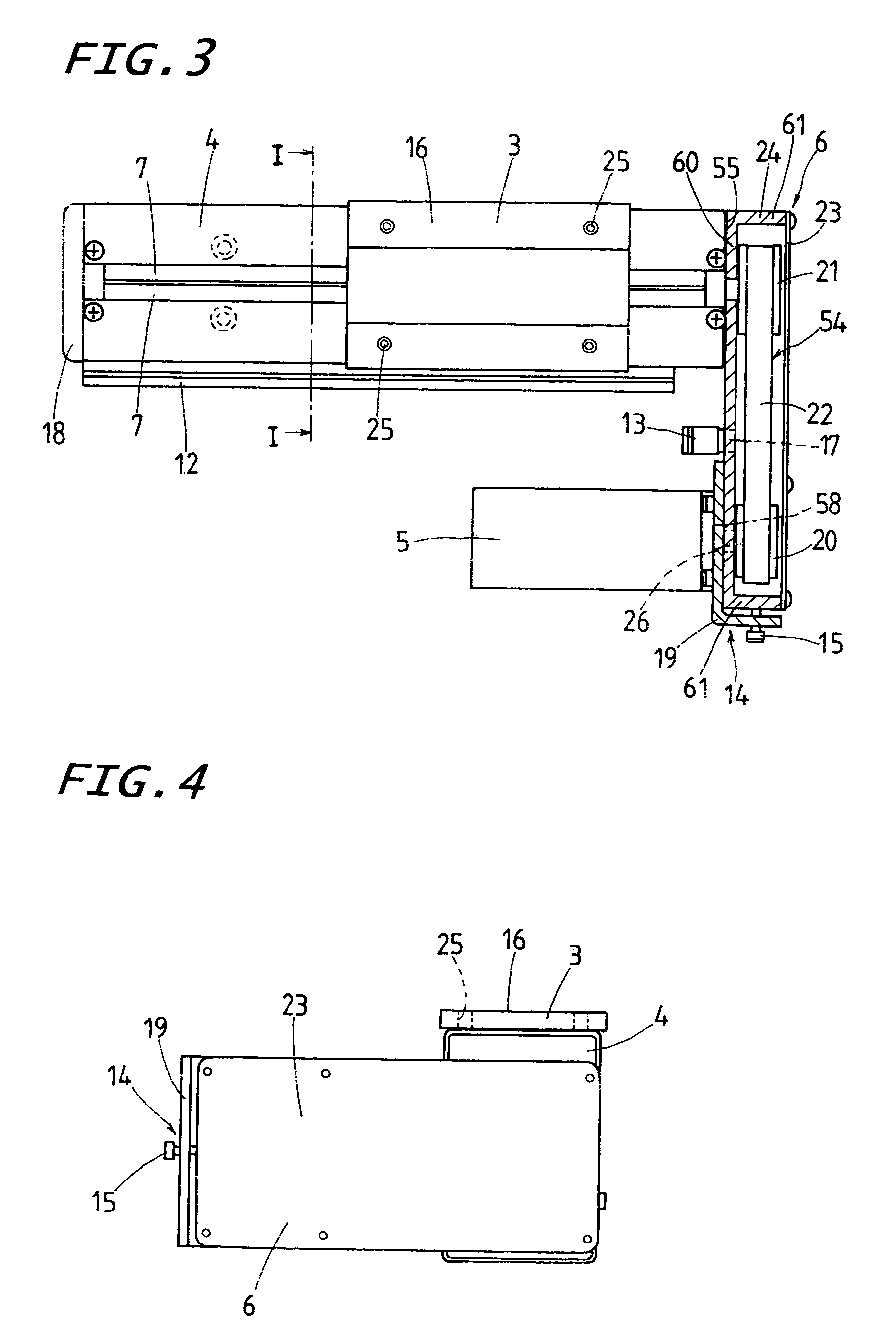
[0036]Referring now in detail to the accompanying drawings, a sliding unit having sealing means according to the present invention will be explained below.

[0037]A constructional feature of the sliding device of the present invention are envisaged operating on a diversity ...


PUM


Abstract

A sliding device for use with a variety of machines is reduced in overall length, thereby being compact in construction. The sliding device has a drive train enclosure made airtight and is acceptable for use in a clean environment. The sliding device includes an elongated sliding unit enclosure of airtight construction, a sliding table and a driving motor that is coupled to the drive train enclosure in parallel with the sliding unit enclosure. The drive train enclosure receives a drive train to carry power from the driving motor to the sliding table. The drive train enclosure is mounted with the driving motor while maintaining airtightness.

Description

FIELD OF THE INVENTION[0001]The present invention relates to a dust proof sliding device causing little dust, which is comprised of an elongated sliding unit enclosure made in airtight construction with sealing members, a sliding table movable along the sliding unit enclosure and a driving motor actuating the sliding table.BACKGROUND OF THE INVENTION[0002]There have been conventionally known the sliding devices of a completely enclosed type that is adapted for use in the semiconductor manufacturing machines, machine tools, assembly machines, testing machines, and so on, which are needed to operate in the clean rooms. A prior sliding device of the type stated earlier is disclosed in, for example Japanese Patent Laid-Open No. 2003-222129, in which sealing members of foam rubber fit in seal holders that are each made up of a seal support portion and a cover portion integral with the seal support portion, the seal holders being attached at their cover portions onto widthwise opposite si...

Claims


Application Information

Patent Timeline
Patent Type & Authority Patents(United States)
IPC IPC(8): F16H19/02B65G69/18F16C29/08F16H7/02F16H7/08F16H25/20F16H25/24
CPCF16C29/08Y10T74/18712Y10T74/1872Y10T74/18576
Inventor KATO, MASATAKA
Owner NIPPON THOMPSON
Learn More