Flexible intra-oral x-ray imaging device

a flexible, intra-oral technology, applied in the direction of radiological control devices, instruments, television systems, etc., can solve the problems of limiting the ability of dental practitioners to correctly position electronic sensors in patients' mouths, discomfort for certain patients, and increased difficulty in reducing discomfort for patients

Active Publication Date: 2009-07-21
SIRONA DENTAL
View PDF35 Cites 61 Cited by
  • Summary
  • Abstract
  • Description
  • Claims
  • Application Information

AI Technical Summary

Benefits of technology

[0017]The present invention addresses the deficiencies in the prior art discussed above, by providing a flexible, electronic x-ray imaging device that fits partially or wholly within a patient's mouth. The imaging device or sensor includes a flexible portion, which advantageously reduces the level of discomfort for the patient, and a rigid portion, which includes complementary circuitry.

Problems solved by technology

Firstly, electronic sensors are more sensitive to x-rays than is x-ray film.
However, the sensors of the '942 patent and other conventional sensors utilize single-crystal silicon-based technologies, which produce fragile and rigid imaging devices, thus necessitating the use of rigid housing materials.
Therefore, conventional sensor units usually are non-compliant or unbendable, which may cause discomfort for certain patients and limit a dental practitioner's ability to correctly position such a sensor unit in a patient's mouth.
Another problem with current electronic sensing systems is their high cost.
Solid-state devices such as CCDs have imperfect manufacturing yields and require nearly perfect charge generation efficiency to achieve a good image comparable in quality those achievable with x-ray film.
However, CCDs and CMOS imaging devices for x-ray sensor applications utilize extremely sophisticated equipment and processing procedures, and these imaging devices are inherently expensive to develop and manufacture.
The conventional TFT process, however, is much too hot to be used with plastics, and CMOS and CCD processes are similarly unsuitable.
This strategy, however, may be unsuitable for a sensor whose entire electronic packaging must fit within a patient's mouth.
Moreover, this strategy may be unsuitable if the sensor is to operate as a wireless sensor.
This approach, however, utilizes conventional semiconductor processing techniques and, therefore, is unsuitable for use with plastic materials.
As evident from the above discussion, a number of technical hurdles limit the development of a flexible intra-oral dental sensor.

Method used


Image

  • Flexible intra-oral x-ray imaging device
  • Flexible intra-oral x-ray imaging device
  • Flexible intra-oral x-ray imaging device

Examples


Embodiment Construction

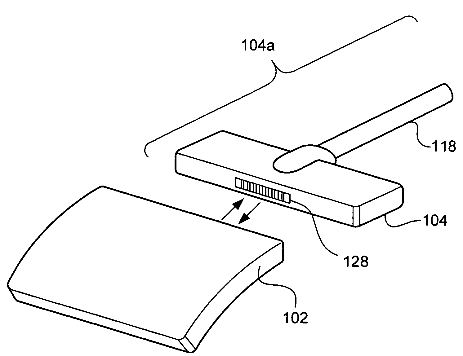
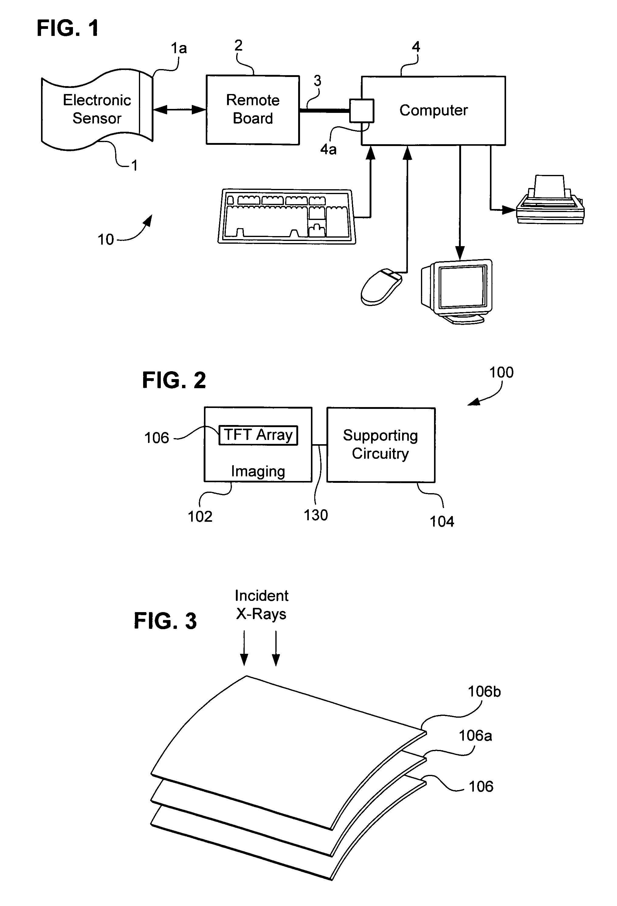
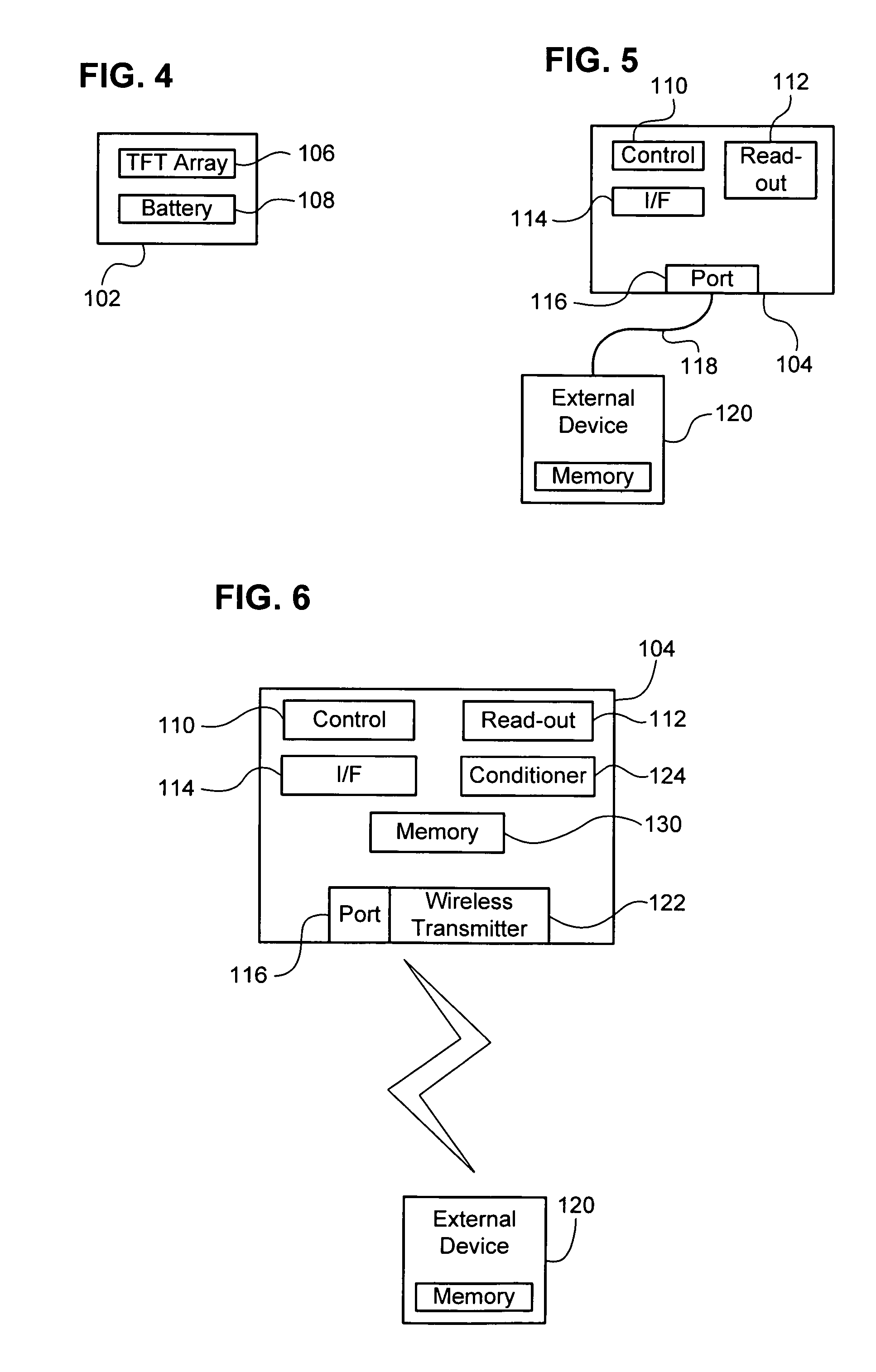
[0034]FIG. 2 schematically shows components of an intra-oral x-ray sensor 100 according to the present invention. The sensor 100 includes two functional systems: an imaging portion 102 and a supporting-circuitry portion 104. During operation, the imaging portion 102 is positioned inside a patient's mouth and oriented to receive incident x-ray radiation. Preferably, the imaging portion 102 is flexible, compliant, and constructed of component circuitry such as an array of flexible TFTs 106. Preferably, each TFT in the array 106 corresponds to a pixel of a captured image. Optionally, the supporting-circuitry portion 104 also fits within the patient's mouth during an image-capturing operation. The imaging portion 102 and the supporting-circuitry portion 104 are interconnected by a connector 130, which may be rigid or flexible. Other connection arrangements are discussed below.

[0035]The TFT array 106 may be fabricated using any known technique for low-temperature deposition of thin films...


PUM


Abstract

An electronic x-ray imaging sensor that flexibly fits within a patient's mouth includes a flexible portion and a rigid portion. The flexible portion includes an array of detection devices, and the rigid portion includes complementary circuitry for controlling and / or obtaining image data from the array. The flexible portion may be detachable from the rigid portion, which allows the flexible portion to be disposable while the detachable portion is reusable.

Description

BACKGROUND OF THE INVENTION[0001]1. Field of the Invention[0002]The present invention generally relates to a filmless intra-oral dental device for detecting or sensing x-rays. More particularly, the present invention relates to a flexible electronic x-ray sensing device that fits inside a patient's mouth.[0003]2. Related Art[0004]Dentists and oral surgeons typically use x-ray radiation to obtain images of intra-oral regions, which aid in diagnosis and treatment of dental disorders. Most conventional x-ray detection techniques use photosensitive film (“x-ray film”) to register an image. For example, in conventional x-ray detection, a film cartridge is inserted in a patient's mouth and, when the cartridge is exposed to x-rays, the x-ray film is exposed and captures an image of an intra-oral region, such as the patient's teeth and / or gums. The x-ray film subsequently undergoes chemical development to make the image on the exposed x-ray film readily visible.[0005]In digital or electroni...

Claims


Application Information

Patent Timeline
Patent Type & Authority Patents(United States)
IPC IPC(8): A61B6/14H05G1/64
CPCA61B6/145A61B6/4233G01T1/2018G01T7/00G01T1/244A61B6/4423G03B42/042H04N5/32H04N5/3696H04N25/702
Inventor MANDELKERN, STANMICHAELI, DANIELSLOVIN, JEFFREY
Owner SIRONA DENTAL
Why Eureka
Try Eureka