
Wurster fluid bed coater with fluidizing gas distribution plate bypass

a technology of fluidizing gas and coater, which is applied in the direction of sweetmeats, lighting and heating apparatus, furnaces, etc., can solve the problems of not receiving the same uniform coating, not uniformly cycled through the coating process, and not properly returning

Active Publication Date: 2009-07-21
SPRAYING SYST
View PDF2 Cites 1 Cited by
  • Summary
  • Abstract
  • Description
  • Claims
  • Application Information

AI Technical Summary

Benefits of technology

The present invention provides a solution for preventing uneven or incomplete circulation of product in a Wurster coater without the need for a separate source of pressurized gas. This is achieved by creating a cavity above the outer portion of the gas distribution plate and directing a bypass flow portion of the fluidizing gas at relatively higher velocity to sweep product from the junction formed by the bowl wall with the fluidizing gas distribution plate. The invention also includes adjusting the position of the distribution plate to control the volume and velocity of the bypass gas stream passing through the bypass cavity and radially inward into the chamber at the lower rim of the bowl. This allows for optimal velocity of the bypass gas and gentle push of product into the Wurster tube. The invention aims to overcome deficiencies of the prior art and achieve this objective without causing sudden or sharp changes in the gas environment within the fluid bed bowl.

Problems solved by technology

These and other prior patents have acknowledged that heavier tablets do not uniformly cycle through the coating process.
Those particles which are thus delayed or caused to lodge in this region of slower-moving gas do not properly return to the main circulation of product flow into the up-bed region of the Wurster tube and do not receive the same uniform coating as the balance of the product flow.
However, the inventors have found this modification to be sometimes ineffective by itself for certain kinds of processes and products, particularly for the manufacture of coated tablets.
However, the solution proposed by U.S. Pat. No. 6,597,365 has its own inherent disadvantages.
Because the compressed air issuing from such a separate external source is not necessarily at the same temperature and degree of dryness as the carefully conditioned main fluidizing stream of gas being drawn through the coating chamber, it has the potential of unbalancing and thus upsetting the pressure and temperature of the entire coating environment.
In addition, the injection of outside air under a significant pressure differential also presents the danger of particle or tablet attrition by reason of the particles or tablets being knocked violently against each other, thereby causing them to be worn down, chipped, or even broken apart.

Method used


Image

  • Wurster fluid bed coater with fluidizing gas distribution plate bypass
  • Wurster fluid bed coater with fluidizing gas distribution plate bypass
  • Wurster fluid bed coater with fluidizing gas distribution plate bypass

Examples


Embodiment Construction

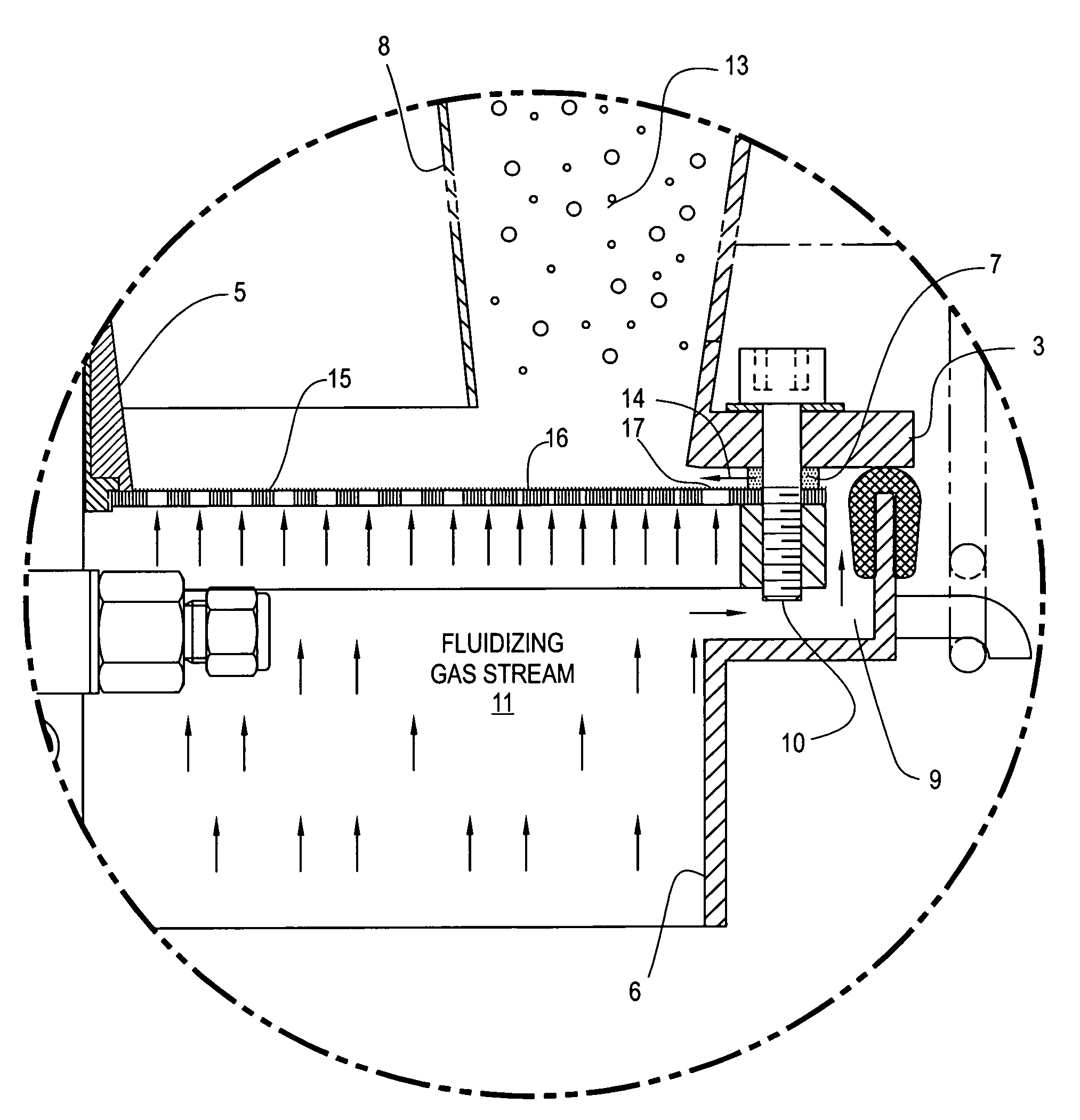
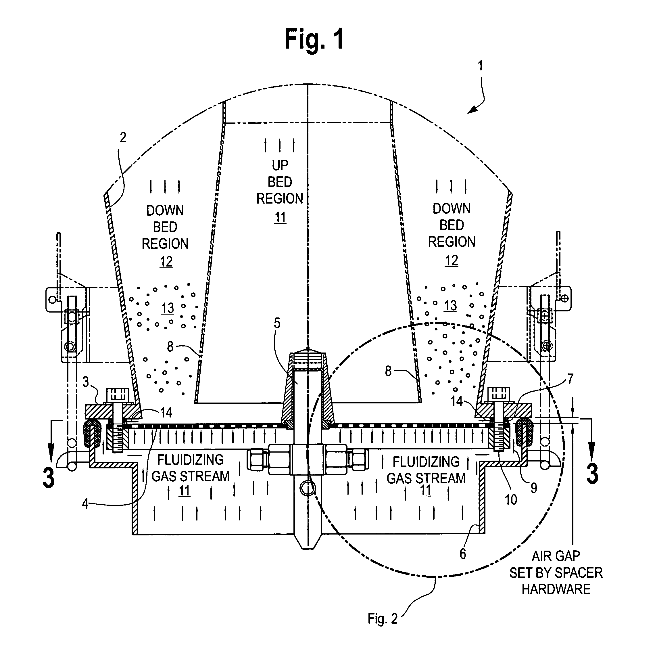
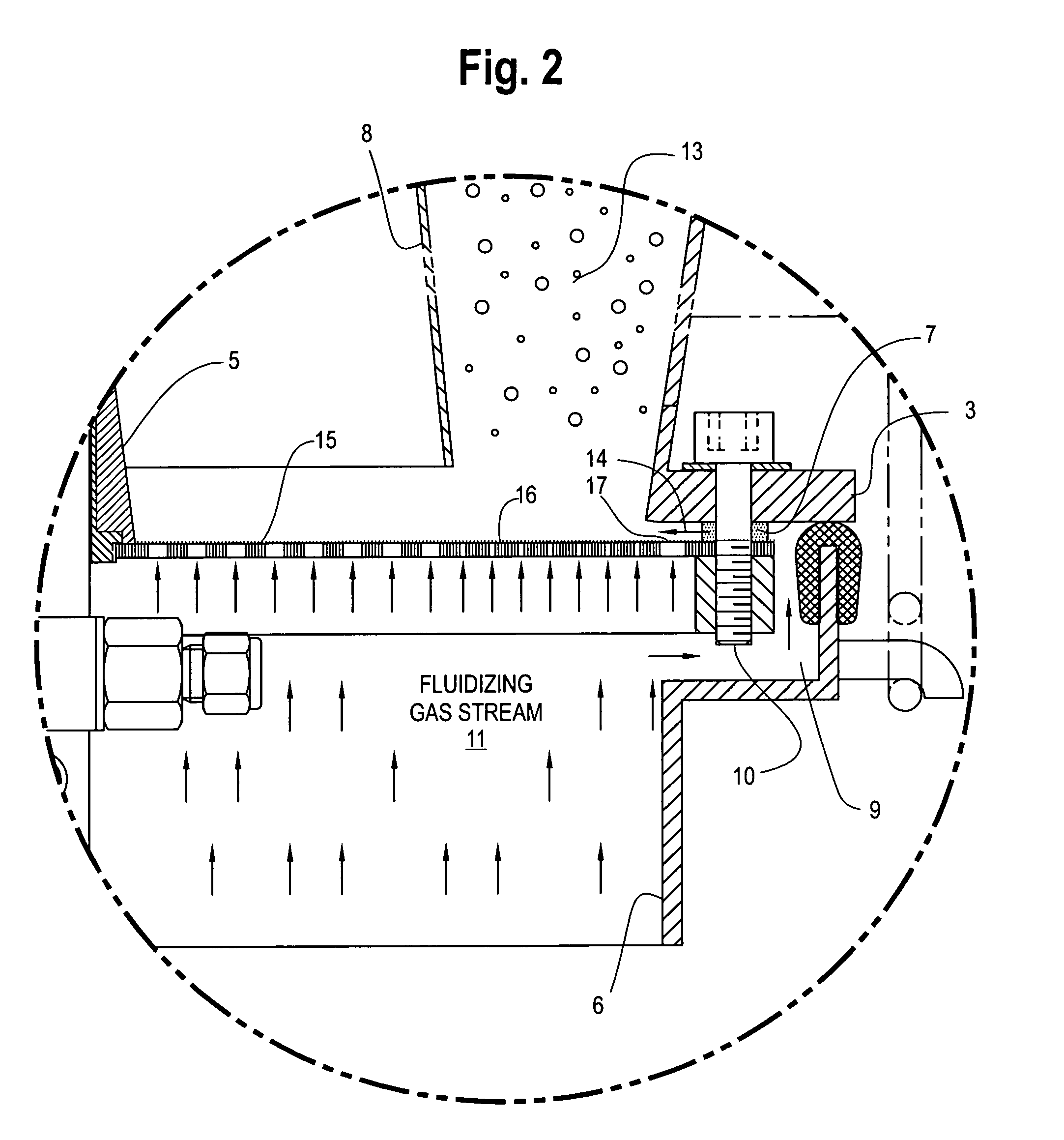
[0017]FIGS. 1 and 2 show a Wurster coater incorporating the improvements of the present invention. In common with prior art Wurster devices, the fluid bed coating device comprises a fluid bed bowl 1 having a cylindrical outer wall 2 terminating in a lower flange 3, and a perforated fluidizing gas distribution plate 4 above a plenum 6. Within the chamber above the bowl is a vacuum fan (not shown) and a product filter system (not shown) for retaining the coated product particles. The plenum is separate from the bowl and can be raised or lowered relative to the bowl for sealing the bowl against the upper filter chamber (not shown) for gaining access to the chamber's internal elements. The distribution plate 4 is held in place by holding hardware 10 including spacer washers 7 which draws it up against the bottom flange 3 of the fluid bed bowl.

[0018]For coating a product, the fluid bed bowl is commonly equipped with one or more individual Wurster tubes 8, each of which creates an up-bed ...


PUM


Abstract

An improved Wurster coater in which conditioned fluidizing gas, drawn through a coating chamber bowl from a plenum by a vacuum fan, is directed through a perforated gas distribution plate through one or more Wurster tubes. The perforated gas distribution plate defines three concentric gas flow zones: a central high-flow up-bed zone beneath the Wurster tube, a surrounding annular lower-flow down-bed zone, and an outer peripheral bypass zone defining a bypass cavity underlying the outer lower wall of the bowl. A controlled bypass flow of conditioned fluidizing gas is directed into the bypass zone, either around the edge of the distribution plate or through relatively larger holes in its plate's outer periphery, which causes that portion of the fluidizing gas to flow radially inward across the distribution plate, thereby sweeping particles away which would otherwise stagnate at the inner corners of the bowl due to low gas velocity in that region. The depth of the cavity is adjustable for varying the pressure drop, and thereby the volume and velocity, of the bypass gas stream.

Description

BACKGROUND OF THE INVENTION[0001]The present invention relates to an improved method and apparatus for controlling movement of product to be coated from the down-bed region to the up-bed region of a Wurster-type fluid bed coater. The well-known Wurster apparatus and process is used for coating particulate material (such as powders, granules, seeds, beads, pellets or tablets) in a batch fluidized bed dryer. The fluid bed is widely used for drying powders, creating granules via agglomeration, or coating powders, granules or tablets of pharmaceutical, food and chemical ingredients.DESCRIPTION OF THE PRIOR ART[0002]The Wurster coating process relies upon a continuous conditioned gas stream which moves the product (such as powders, granules, seeds, beads, pellets or tablets) past one or more spray nozzles for purposes of coating, layering, and ultimately drying the finished product. Conditioning of the gas stream to maintain a specified temperature and humidity is essential for creating ...

Claims


Application Information

Patent Timeline
Patent Type & Authority Patents(United States)
IPC IPC(8): B05C5/00A23G3/26B01J8/18B05C11/06
CPCB05C19/02B01J2/16B01J2/006
Inventor BENDER, MARTIN P.SZCZAP, JOSEPH P.VERBARG, DONALD P.
Owner SPRAYING SYST
Features
  • Generate Ideas
  • Intellectual Property
  • Life Sciences
  • Materials
  • Tech Scout
  • Unparalleled Data Quality
  • Higher Quality Content
  • 60% Fewer Hallucinations
Learn More