High magnetostriction of positive magnetostrictive materials under tensile load

a technology of positive magnetostrictive materials and tensile load, applied in the field of magnetostriction, can solve the problems that conventional methods do not work for positive magnetostrictive materials under tensile load

Inactive Publication Date: 2009-07-21
THE UNITED STATES OF AMERICA AS REPRESENTED BY THE SECRETARY OF THE NAVY
View PDF36 Cites 64 Cited by
  • Summary
  • Abstract
  • Description
  • Claims
  • Application Information

AI Technical Summary

Benefits of technology

[0012]The present invention represents a unique methodology for using a positive magnetostrictive material under tensile loading. The conventional methodology for operating a positive magnetostrictive material in a device involves utilization of an excitation coil so as to supply an axial magnetic field to a magnetostrictive rod (or other elongate structure). This conventional methodology does not work for positive magnetostrictive materials under tensile load, since the magnetization is often already along the axial direction. The present invention applies a transverse (e.g., circumferential or tangential) magnetic field to magnetostrictie material with respect to which tensile stress is being exerted. The generation of a transverse magnetic field is accomplished according to at least one of three inventive modes. This transverse magnetic field rotates the magnetostrictive material's magnetization from the axial direction to the transverse direction, resulting in the desired magnetostrictive effect.

Problems solved by technology

This conventional methodology does not work for positive magnetostrictive materials under tensile load, since the magnetization is often already along the axial direction.

Method used


Image

  • High magnetostriction of positive magnetostrictive materials under tensile load
  • High magnetostriction of positive magnetostrictive materials under tensile load
  • High magnetostriction of positive magnetostrictive materials under tensile load

Examples


example 1

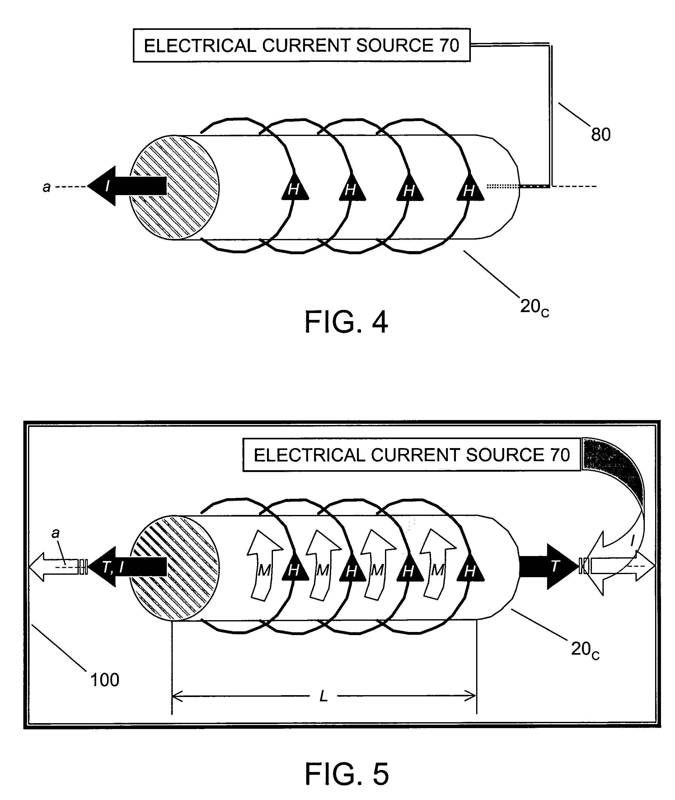
[0050]With reference to FIG. 4 and FIG. 5, in this example the voltage is applied directly to the magnetostrictive material 20c. A load of 40 lb=178 N is applied to a magnetostrictive, electrically conductive wire 20c of single crystal (or highly textured) Fe81Ga19 that is 3 mm (˜⅛ inch) in diameter and 10 meters in length. To calculate the cross-sectional area a of magnetostrictive wire 20c, a=πr2=7.07×10⁻⁶ m2. The resistance R of Fe81Ga19 wire=ρ=10 m / a=1.06 Ω. Force F=178 N. The tensile stress T=25.2 MPa. Setting the magnetic and mechanical energies equal, the following equation obtains: M×H=T×Sms. The magnetic field needed, Hav, is calculated as follows: Hav=25.2×106 Pa×300×10−6 / 1.7 T=4450 A / m. The magnetic field at the surface, Hsurface, is assumed to be ≅1.2>Hav=5340 A / m. The current needed is calculated as follows: I=5340 A / m×π0.3×10⁻² m=50.3 A. Voltage V=IR=50.3 A×1.06 Ω=53.3 V. Power P=VI=53.3 V×50.3 A=2680 W. Thus, in this case of a small diameter (3 mm), 10 meter Fe81Ga19 ...

example 2

[0051]With reference to FIG. 6 and FIG. 9, in this example a load of 40 lb=178 N is applied to the present invention's integral configuration 40, a cable-like structure that includes a Cu wire core 300 (1.5 mm in diameter) and, surrounding Cu wire 300, a magnetostrictive ring (annulus) 200 (10 meters in length, 3 mm in diameter) made of Fe81Ga19 textured magnetostrictive alloy. Core 300 has a radium of rin; annulus 200 has a radius of rout. The cross-sectional area a of the annular active material 200 is calculated as a=π(rout2−rin2)=5.3×10⁻⁶ m2. The resistance R of the Cu wire is calculated as R=0.102 Ω. The force F=178 N. The tensile stress T=33.6 MPa. Setting the magnetic and mechanical energies equal, the following equation obtains: M×H=T×Sms. Magnetic field Hav, the magnetic field needed in the Fe81Ga19 ring 200, is calculated as follows: Hav=33.6×106 Pa×300×10−6 / 1.7=5930 A / m=74.2 Oe. To achieve this, magnetic field Hsurface, the magnetic field at the surface of the copper wire...

example 3

[0052]Still with reference to FIG. 6 and FIG. 9, in this example the Cu wire 300 and the Fe81Ga19 annulus 200 each have twice the diameter as in Example 2. In addition, in this example a larger load of 100 lb=445 N is applied to the present invention's integral configuration 40, which includes Cu core 300 (3 mm in diameter) and Fe81Ga19 annulus 200 (10 meters in length, 6 mm in diameter). The cross-sectional area a of the annular active material 200 is calculated as a=π(rout2−rin2)=2.12×10⁻⁵ m2. The resistance R of the Cu wire is calculated as R=0.0255 Ω. The force F=445 N. The tensile stress T=21 MPa. Setting the magnetic and mechanical energies equal, the following equation obtains: M×H=T×Sms. Magnetic field Hav, the magnetic field needed in the Fe81Ga19 ring 200, is calculated as follows: Hav=21×106 Pa×300×10−6 / 1.7 T=3710 A / m=46.6 Oe. To achieve this, magnetic field Hsurface, the magnetic field at the surface of the copper wire core 300, is assumed to be ≅1.5×Hav=5570 A / m. The cu...


PUM

PropertyMeasurementUnit
diameteraaaaaaaaaa
diameteraaaaaaaaaa
diameteraaaaaaaaaa

Abstract

An elongate structure having a magnetostrictive material composition is subjected to tensile stress in the longitudinal-axial direction, thereby generally orienting the magnetization of the elongate structure in the longitudinal-axial direction. Electrical current is conducted through the elongate structure and / or through at least one adjacent elongate conductor, thereby generally orienting the magnetization of the elongate structure in the transverse direction, generally in parallel with the transverse direction of the magnetic field concomitant the conduction of current through the elongate structure. The elongate structure magnetostrictively contracts due to the (generally 90°) repositioning of the magnetization of the elongate structure. Examples of inventive configurational variants include: (i) an elongate structure itself conducting current; (ii) a hollow elongate structure accommodating placement therethrough of at least one elongate conductor; (iii) an elongate structure flanked by a pair of elongate conductors conducting current in opposite directions; (iv) plural elongate structures bordering a centralized elongate conductor.

Description

CROSS-REFERENCE TO RELATED APPLICATIONS[0001]This application claims the benefit of U.S. provisional application No. 60 / 543,650, filed 12 Feb. 2004, hereby incorporated herein by reference, entitled “Preparation of Positive Magnetostrictive Materials for Operation under Tension,” joint inventors Arthur E. Clark, James B. Restorff and Marilyn Wun-Fogle.[0002]This application is related to U.S. nonprovisional application No. 11 / 007,953, filed 7 Dec. 2004, hereby incorporated herein by reference, entitled “Magnetostrictive Materials, Devices and Methods using High Magnetostriction, High Strength Fe-Ga Alloys,” joint inventors Arthur E. Clark, James B. Restorff and Marilyn Wun-Fogle; which is a continuation of U.S. nonprovisional application No. 10 / 182,095, filed 24 Jul. 2002, hereby incorporated herein by reference, entitled “Magnetostrictive Materials, Devices and Methods using High Magnetostriction, High Strength Fe-Ga Alloys,” joint inventors Arthur E. Clark, James B. Restorff and M...

Claims


Application Information

Patent Timeline
Patent Type & Authority Patents(United States)
IPC IPC(8): H01L41/00H02N2/00
CPCH01F1/147H01L41/47H01L41/20H10N35/85H10N35/01
Inventor CLARK, ARTHUR E.RESTORFF, JAMES B.WUN-FOGLE, MARILYN
Owner THE UNITED STATES OF AMERICA AS REPRESENTED BY THE SECRETARY OF THE NAVY
Why Eureka
Try Eureka